

SDS5000X Series
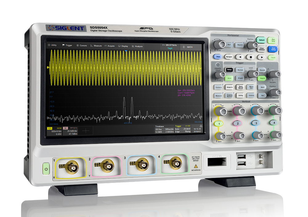
Four-channel oscilloscopes with 350 MHz, 500 MHz or 1 GHz bandwidth, 5 GSa/s, 250 Mpts of memory per channel and 110,000 waveforms per second, on a 10.1-inch touchscreen. Add the SPL2016 logic probe and it becomes a mixed-signal oscilloscope with 16 digital channels.
A gigahertz on the bench, and the memory to use it
Bandwidth shows you the edge; memory decides for how long you can keep looking at it. The SDS5000X stores 250 Mpts per channel, which is 50 ms of signal at the full 5 GSa/s. An instrument with 10 Mpts would have to drop to 200 MSa/s to cover the same 50 ms, and the detail you zoom in for would be gone. Here the whole start-up of a converter, or a long bus transaction, is captured once and examined afterwards.
Siglent’s SPO acquisition shows up to 110,000 waveforms per second with 256-level intensity grading, and 500,000 per second in Sequence mode. A digital trigger system with thirteen trigger types, zone trigger and serial triggers isolates the event; History keeps up to 100,000 frames so you can go back to it.
More than 60 measurements with statistics, a 2 Mpts FFT, Bode plot, hardware mask test and decoding of I²C, SPI, UART, CAN and LIN are standard. Power analysis and nine further serial protocols are software keys. Three four-channel models make up the series today; for 12-bit resolution or more than four channels there is the SDS5000X HD.
What defines the series
1 GHz at 5 GSa/s
Rise time 0.4 ns on the SDS5104X, 0.7 ns and 1.0 ns on the 500 and 350 MHz models. 5 GSa/s with one channel of each pair in use, 2.5 GSa/s with all four.
250 Mpts per channel
Enough for 50 ms at the full sample rate. Hardware zoom lets you pick a slow time base without giving up the sample rate, then zoom in on the detail.
110,000 waveforms per second
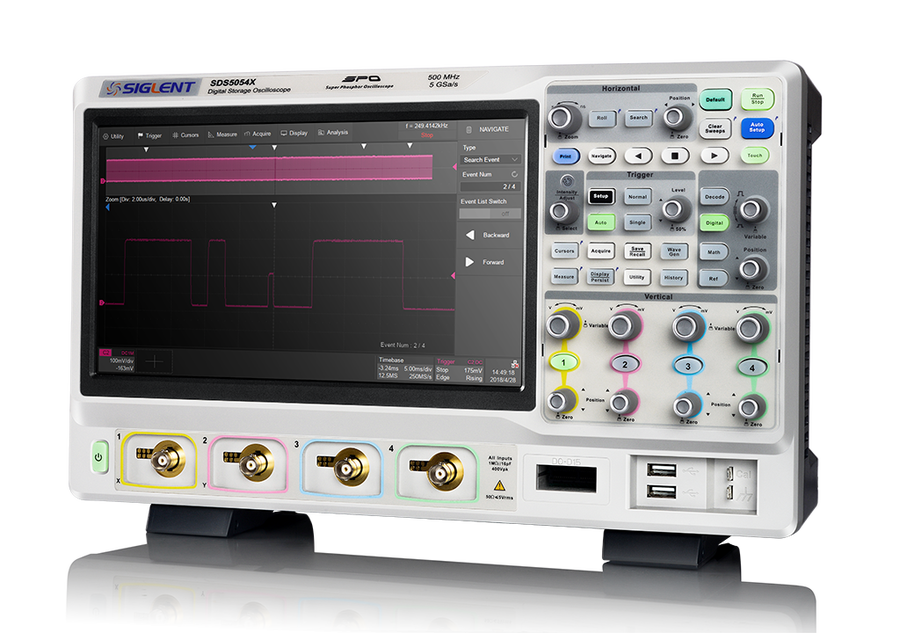
And 500,000 in Sequence mode. With 256-level intensity grading and a history of up to 100,000 frames, the event that happens once in a while is on the screen and can be replayed.
A trigger for the awkward event
Thirteen trigger types, zone trigger and serial bus triggers on a digital trigger system with less than 9 ps RMS jitter (typical).
Three models
The same instrument in three bandwidths. Sample rate, memory, triggers and analysis are identical; the bandwidth sets the rise time and the fastest time base. Prices exclude VAT.
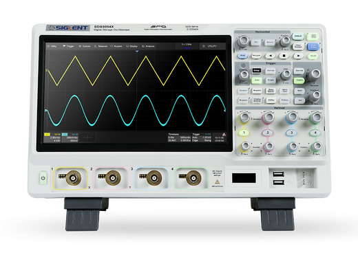
Rise time 1.0 ns, time base from 1 ns/div.
Rise time 0.7 ns, time base from 500 ps/div.
Rise time 0.4 ns, time base from 200 ps/div.
Side by side
| SDS5034X | SDS5054X | SDS5104X | |
|---|---|---|---|
| Bandwidth | 350 MHz | 500 MHz | 1 GHz |
| Rise time (typ.) | 1.0 ns | 0.7 ns | 0.4 ns |
| Fastest time base | 1 ns/div | 500 ps/div | 200 ps/div |
| Upgrade by software key | to 500 MHz | to 1 GHz | top model |
| Price, excl. VAT | €2,869 | €4,959 | €6,359 |
Choose the bandwidth when you buy. A key can raise it later, but an SDS5034X with the 500 MHz key costs €929 more than an SDS5054X, and an SDS5054X with the 1 GHz key €659 more than an SDS5104X. The SDS5034X cannot be taken to 1 GHz.
Two-channel models. The SDS5032X (350 MHz) · SDS5052X (500 MHz) · SDS5102X (1 GHz) are sold out and no longer part of the current range. Their pages stay online for owners; the bandwidth keys for them are still available.
The instrument at work
Eight screens from the SDS5000X, each with what it shows. Select a picture to open it full size.
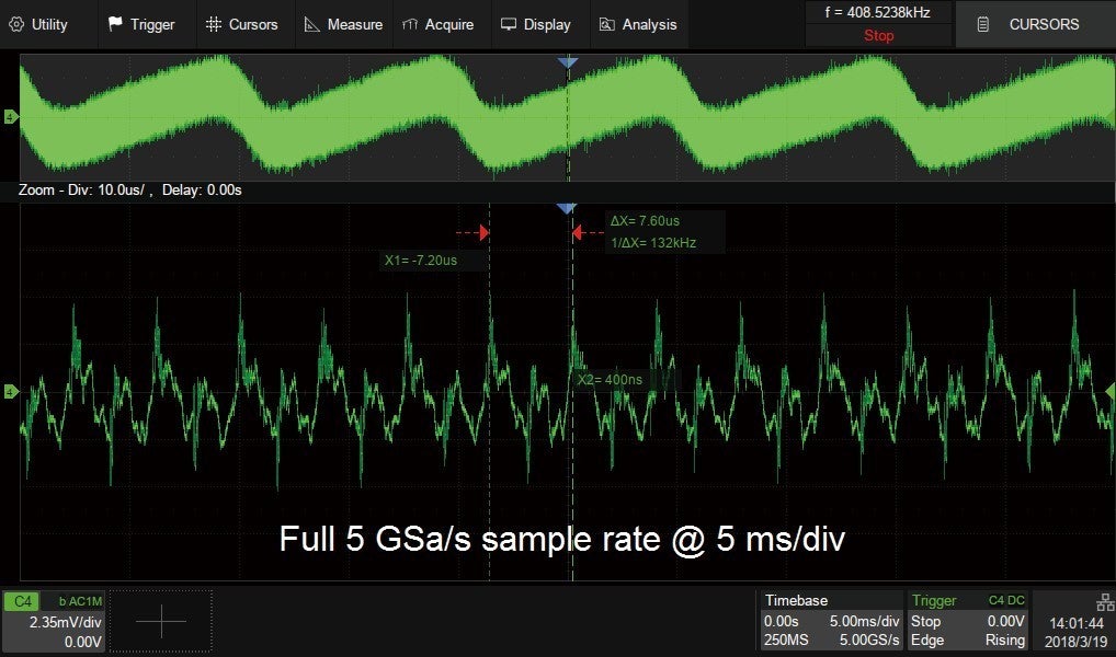
Deep memory: 5 GSa/s at 5 ms/div
250 Mpts hold 50 ms of signal at the full 5 GSa/s. The lower window is a zoom to 10 µs/div out of the same acquisition, with cursors 7.6 µs apart.
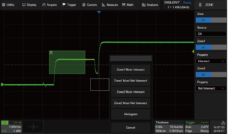
Zone trigger
Two boxes drawn on the screen: the trace must cross zone 1 and must not touch zone 2. A condition that would take a nested trigger set-up is drawn with a finger.
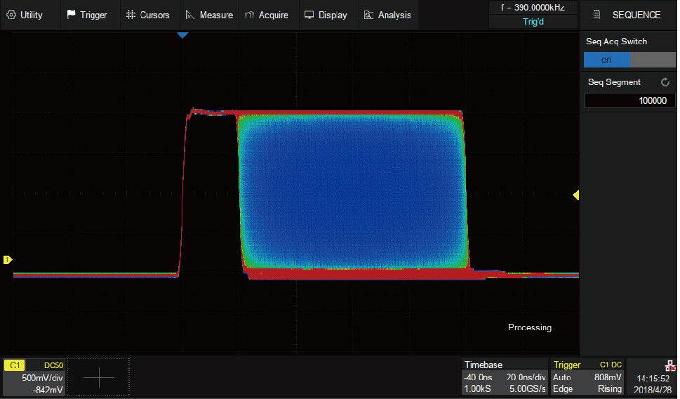
Sequence mode
100,000 segments captured back to back and overlaid with colour grading. The dead time between two triggers can be as short as 2 µs.
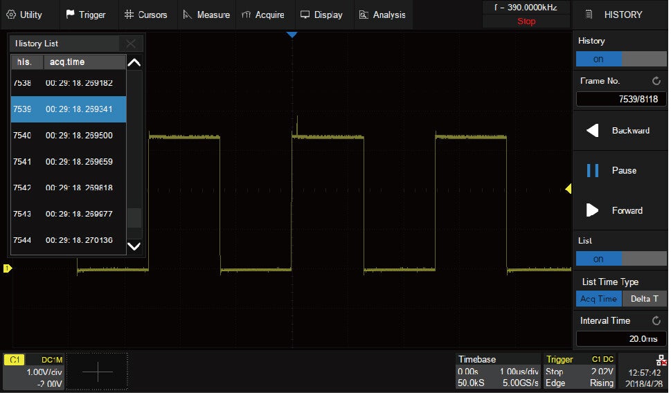
History
Frame 7,539 of 8,118 with its acquisition time: the list lets you step back to the one frame that carries the glitch, after the event has passed.
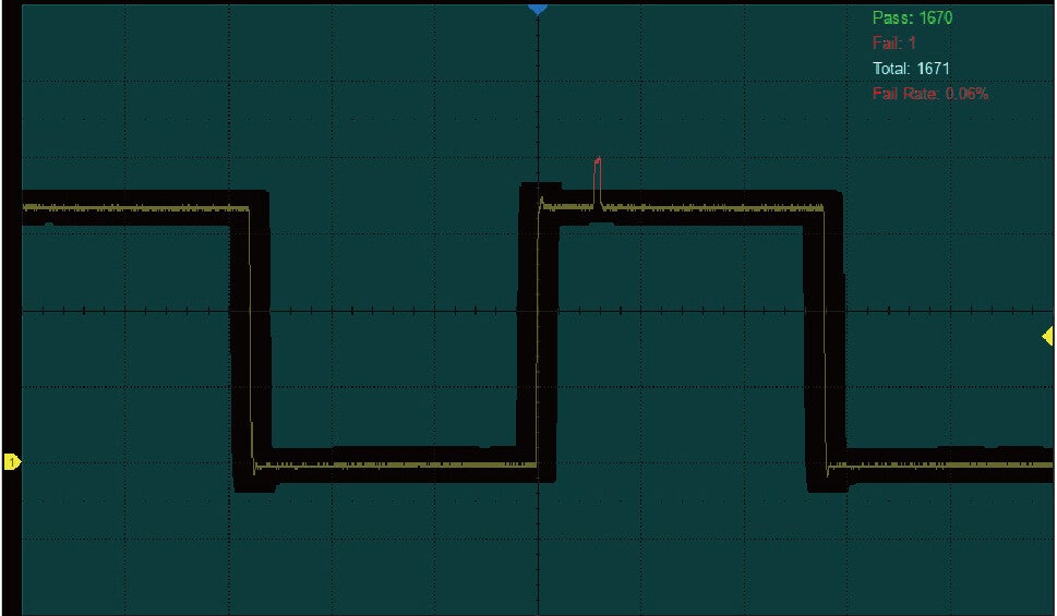
Hardware mask test
1,671 waveforms tested, one failure, fail rate 0.06 %. The spike that broke the mask is on the screen. Up to 18,000 pass/fail decisions per second.
Serial decode with event list
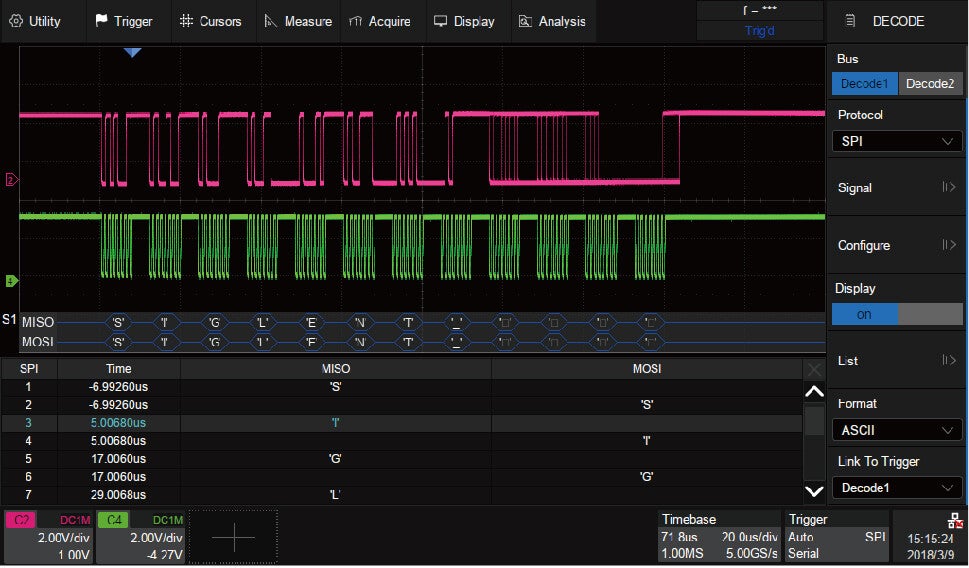
SPI on two channels: MISO and MOSI decoded as ASCII under the waveforms and listed with time stamps in the table. Two buses can be decoded at once.
FFT
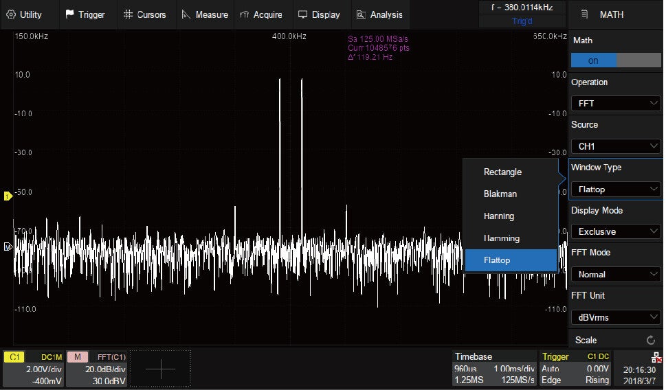
A one-million-point FFT in dBVrms with a choice of five windows; the frequency resolution here is 119 Hz. The FFT runs on up to 2 Mpts.
Measurements with statistics
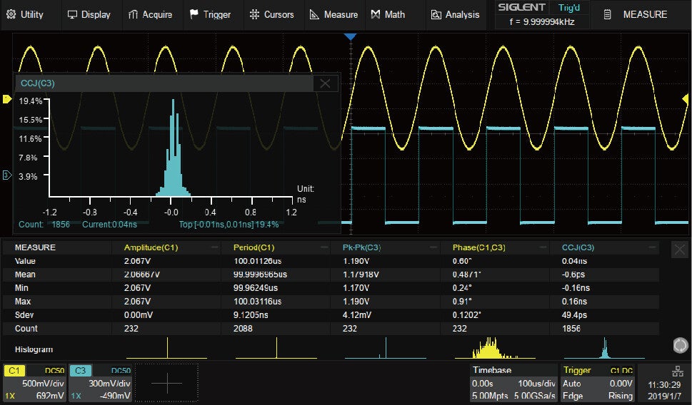
Five parameters with mean, minimum, maximum, standard deviation and count, and a histogram of the cycle-to-cycle jitter on channel 3.
Front and rear
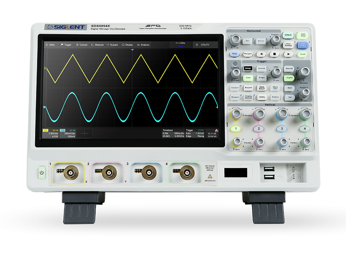
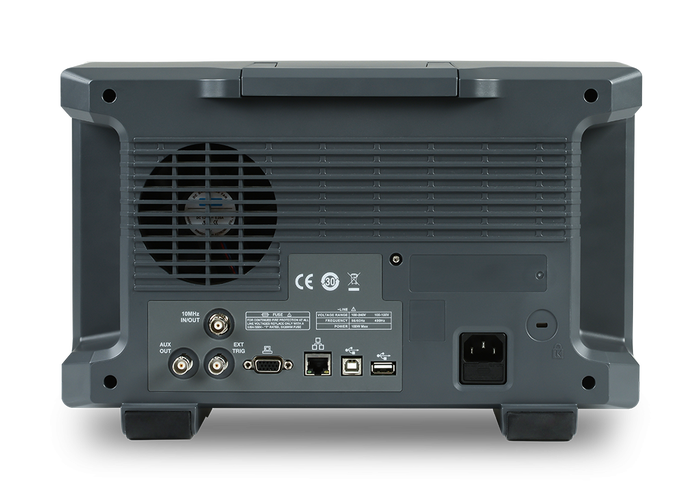
A bench instrument of 370 × 144 × 231 mm and 4.0 kg, with every connection you need for a test system at the back.
Options and accessories
Software keys are activated on the instrument you already own. The licences page explains each one in detail. Prices exclude VAT.
Bandwidth upgrades
One key per step. The 350 MHz model can go to 500 MHz, the 500 MHz model to 1 GHz.
| Order code | Option | Price | |
|---|---|---|---|
| SDS-5000X-4BW05 | 350 MHz → 500 MHz, for the SDS5034X | €3,019 | View |
| SDS-5000X-4BW10 | 500 MHz → 1 GHz, for the SDS5054X | €2,059 | View |
| SDS-5000X-2BW05 | 350 MHz → 500 MHz, for the two-channel SDS5032X | €2,829 | View |
| SDS-5000X-2BW10 | 500 MHz → 1 GHz, for the two-channel SDS5052X | €1,359 | View |
Analysis and serial decode
I²C, SPI, UART, CAN and LIN are standard and need no key. Two buses can be decoded at the same time.
| Order code | Option | Price | |
|---|---|---|---|
| SDS-5000X-PA | Power analysis: power quality, harmonics, inrush, switching loss, slew rate, modulation, output ripple, turn-on / turn-off, transient response, PSRR, efficiency, SOA | €759 | View |
| SDS-5000X-CANFD | CAN FD trigger and decode | €289 | View |
| SDS-5000X-FlexRay | FlexRay trigger and decode | €289 | View |
| SDS-5000X-I2S | I²S audio trigger and decode | €289 | View |
| SDS-5000X-1553B | MIL-STD-1553B trigger and decode | €289 | View |
| SDS-5000X-SENT | SENT trigger and decode | €289 | View |
| SDS-5000X-CANXL | CAN XL decode (decode only) | €289 | View |
| SDS-5000X-Manch | Manchester decode (decode only) | €289 | Ask for a quote |
| SDS-5000X-ARINC | ARINC 429 decode (decode only) | €469 | View |
| SDS-5000X-SpaceWire | SpaceWire decode (decode only) | €289 | View |
Hardware that goes with it
Each oscilloscope is supplied with one 500 MHz probe per channel, a USB cable, a power cord, the quick start guide and the calibration certificate.
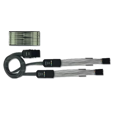
Turns the oscilloscope into a mixed-signal instrument: 16 digital channels at up to 1.25 GSa/s.
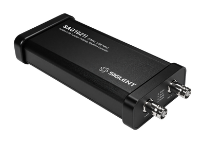
25 MHz function / arbitrary generator controlled by the oscilloscope; also the sweep source for the Bode plot.
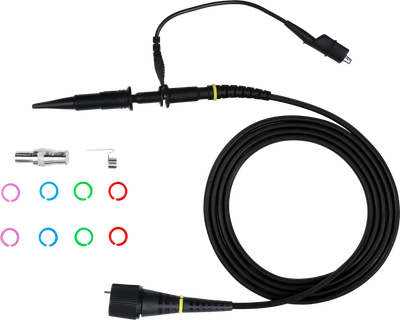
The supplied probes are 500 MHz. The SDS5104X needs this probe or an active probe to use its 1 GHz.

1.2 pF input loading on the SAPBus interface, powered by the oscilloscope.
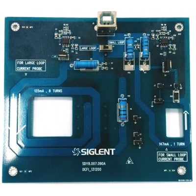
Aligns the voltage and current probes before a switching-loss measurement.
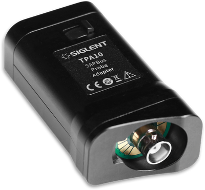
Runs Tektronix TekProbe Level II active probes on the SAPBus input.
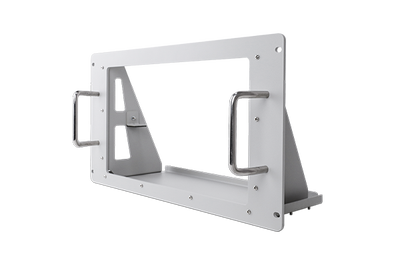
Mounts the bench instrument in a 19-inch rack.
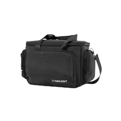
Padded bag with room for the probes and the power cord.
Specifications
From the SDS5000X data sheet EN02F. Where three figures are given they are for the SDS5034X, SDS5054X and SDS5104X in that order.
| Models | |
| Analogue channels | 4 plus external trigger |
| Bandwidth (−3 dB, 50 Ω) | 350 MHz (SDS5034X) · 500 MHz (SDS5054X) · 1 GHz (SDS5104X) |
| Bandwidth at 1 MΩ with probe | 350 MHz · 500 MHz · 500 MHz |
| Rise time (50 Ω, typ.) | 1.0 ns · 0.7 ns · 0.4 ns |
| Time base | 1 ns/div · 500 ps/div · 200 ps/div, each to 1000 s/div |
| Acquisition | |
| Sample rate | 5 GSa/s with one channel of C1/C2 and one of C3/C4 in use · 2.5 GSa/s with both channels of a pair in use |
| Record length | 250 Mpts per channel at 5 GSa/s · 125 Mpts per channel at 2.5 GSa/s |
| Waveform capture rate | Up to 110,000 wfm/s · up to 500,000 wfm/s in Sequence mode |
| Sequence / History | Up to 100,000 segments, 2 µs minimum between triggers · up to 100,000 history frames |
| Acquisition modes | Normal, peak detect (400 ps), average up to 65,536, ERES up to 3 enhanced bits |
| Time base accuracy | ±1 ppm initial, ±1 ppm ageing in the first year |
| Vertical | |
| Vertical scale | 500 µV/div to 10 V/div at 1 MΩ · 500 µV/div to 1 V/div at 50 Ω |
| DC gain accuracy | < 1.5 % at 5 mV/div and above · < 3.0 % below 5 mV/div |
| Bandwidth limit | 20 MHz, 200 MHz |
| Input impedance | 1 MΩ ±2 % parallel 16 pF · 50 Ω ±1 % |
| Maximum input voltage | 400 Vpk (DC + AC, to 10 kHz) at 1 MΩ · 5 Vrms at 50 Ω |
| Channel-to-channel isolation | > 40 dB to 100 MHz · ≥ 34 dB from 100 MHz to the bandwidth |
| Trigger and analysis | |
| Trigger types | Edge, slope, pulse width, window, runt, interval, dropout, pattern, qualified, Nth edge, setup/hold, delay, video; zone trigger with up to 2 zones |
| Trigger jitter | < 9 ps RMS (typ.) |
| Serial trigger and decode | Standard: I²C, SPI, UART, CAN, LIN · options: CAN FD, FlexRay, I²S, MIL-STD-1553B, SENT · decode-only options: CAN XL, Manchester, ARINC 429, SpaceWire |
| Measurements | More than 60 parameters; statistics on up to 12 at once, histogram, trend, gating |
| Math | 2 traces; FFT on up to 2 Mpts, +, −, ×, ÷, integral, derivative, square root and more, with a formula editor |
| Analysis tools | Search, Navigate, History, Mask Test, digital voltmeter, counter, waveform histogram, Bode plot (with SAG1021I or a Siglent SDG) · Power Analysis as an option |
| Digital channels and generator | |
| Digital channels | 16 with the SPL2016 logic probe · up to 1.25 GSa/s · 62.5 Mpts per channel · minimum pulse width 3.3 ns |
| Waveform generator | With the SAG1021I isolated USB module: 1 channel, up to 25 MHz, 125 MSa/s, 14-bit, ±3 V into high impedance |
| General | |
| Display | 10.1-inch TFT, capacitive multi-touch, 1024 × 600; 256-level intensity grading and colour temperature display |
| Interfaces | 3 USB host, 1 USB device (USBTMC), LAN 10/100 (LXI, VXI-11, telnet, socket, web server), AUX out (pass/fail or trigger out), 10 MHz in and out, VGA |
| Power | 100 to 240 V, 50/60 Hz · 100 W maximum, 70 W typical |
| Dimensions and weight | 370 × 144 × 231 mm · 4.0 kg |
| In the box | One SP3050A 500 MHz passive probe per channel, USB cable, power cord, quick start guide, calibration certificate |
Where it is used
Embedded and digital design
Four analogue channels and, with the SPL2016, sixteen digital ones on one time axis. I²C, SPI, UART, CAN and LIN are decoded as standard, with a time-stamped event list.
Fast edges and clocks
1 GHz and a 0.4 ns rise time show what a 100 MHz clock edge really looks like. The SAPBus input powers the SAP1000 active probe for low-loading measurements.
Power electronics
The power analysis option measures switching loss, harmonics, inrush current and efficiency. Deep memory keeps the sample rate over a whole mains cycle.
Production and long-term monitoring
Hardware mask test at up to 18,000 decisions per second with a pass/fail output, History to look back, and LAN control over web browser or SCPI.
Documentation
Firmware and PC software are on the downloads page.
Questions we are asked
Which of the three models do I need?
Look at the fastest edge you have to see, not at the clock frequency. The oscilloscope’s own rise time is 1.0 ns on the 350 MHz model, 0.7 ns at 500 MHz and 0.4 ns at 1 GHz; an edge is shown correctly when it is clearly slower than that. Everything else, sample rate, memory, triggers and analysis, is the same on all three.
Can I upgrade the bandwidth later?
Partly. A software key takes an SDS5034X to 500 MHz (€3,019) and an SDS5054X to 1 GHz (€2,059). The SDS5034X cannot be taken to 1 GHz. Buying the higher model at once is cheaper: by €929 for 500 MHz and by €659 for 1 GHz at today’s prices. With 1 GHz, plan an SP6150A or an active probe, because the supplied probes are 500 MHz.
Is the sample rate always 5 GSa/s?
It is 5 GSa/s when one channel of the pair C1/C2 and one of the pair C3/C4 are in use, so with two channels chosen well. With both channels of a pair switched on the rate is 2.5 GSa/s and the memory 125 Mpts per channel.
Are the 16 digital channels included?
The function is in the instrument; the hardware is the SPL2016 logic probe (€425). With it you get 16 digital channels at up to 1.25 GSa/s, time-aligned with the analogue ones. Early units needed a licence for this (SDS-5000X-16LA); it is still available on the licences page.
Does it have a built-in function generator?
No. The SAG1021I is an external, isolated USB module that the oscilloscope controls: one channel up to 25 MHz. It is also the sweep source for the built-in Bode plot, which works with a stand-alone Siglent SDG generator as well.
Which serial buses can it decode?
I²C, SPI, UART, CAN and LIN are standard, with trigger and decode. CAN FD, FlexRay, I²S, MIL-STD-1553B and SENT are options with trigger and decode. CAN XL, Manchester, ARINC 429 and SpaceWire are options that decode only.
SDS5000X or SDS5000X HD?
The SDS5000X HD is the 12-bit series: four, six or eight channels and 2.5 Gpts of memory, at a higher price. The SDS5000X gives you the same bandwidths and sample rate with four channels and 250 Mpts for considerably less. If you measure small signals on top of large ones, or need more than four channels, look at the SDS5000X HD.
What is in the box, and what is the warranty?
The oscilloscope, one 500 MHz passive probe per channel, a USB cable, a power cord, the quick start guide and the calibration certificate. Siglent instruments bought from siglent.eu carry a 3-year manufacturer’s warranty.
Tell us the signals and we put the set together
The fastest edge, the buses you decode, whether you need digital channels or power analysis. We quote the model with the keys and probes that belong to it. Official Siglent distributor for the EU.
Specifications are taken from the manufacturer’s data sheet and are given for guidance. They can change without notice, and errors and omissions can occur; the official Siglent data sheet is definitive. Contact us to confirm a specification before you order.