

Precision RF cables & adaptors
Sixteen 50 Ω assemblies covering every RF port on the Siglent range — from 4 GHz BNC test leads to 40 GHz precision interfaces. Each one is matched to a specific instrument port, and this page sets out which, and why the distinction matters to your measurement.
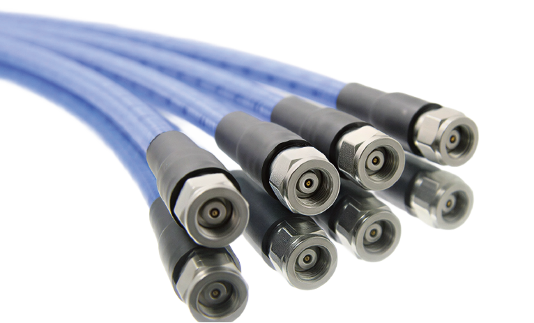
A cable is part of your measurement
At DC a wire is a wire. At radio frequency it is a transmission line, and it has as much influence on the number you read as the setting you dialled in. Every dB the cable absorbs is a dB missing from your signal; every mismatch sends part of the signal back down the line to interfere with what is still arriving.
That matters because the instrument cannot tell the difference. A spectrum analyser reports what arrives at its input connector — it has no way of knowing whether a dip at 12 GHz came from your filter or from a tired lead. Anything the cable does to the signal is attributed to the device under test.
Which is why a cable is worth choosing rather than grabbing. Six things decide whether it is right for the job:

Insertion loss
Every cable throws away part of your signal as heat, and the loss climbs steadily with frequency. A lead that costs you a fraction of a dB at 1 GHz can cost several dB at 18 GHz. On a spectrum analyser that reads directly as amplitude error; on a generator it means less power at the device than the display claims.
Return loss & VSWR
Any mismatch reflects part of the signal back down the cable, where it interferes with the wave still arriving. The result is ripple across your trace — peaks and dips that look like the device under test but belong to the cable. This is the single most common way a cheap lead corrupts a good measurement.
Shielding
A braid with gaps lets your signal leak out and the room leak in. In a shielded lab you may never notice; next to a switching supply, a motor drive, or during EMC work, poor shielding puts signals on your screen that were never in the circuit.
Phase stability
When you bend a cable, its electrical length changes slightly. For amplitude measurements that rarely matters. For a VNA, phase is the measurement — move the cable after calibrating and you have moved the reference plane. Phase-stable cables are built to minimise exactly this.
Bend radius & flex life
Bending a coax tighter than its rated radius permanently deforms the dielectric and the braid. The damage is invisible from the outside and does not heal. Most cables that mysteriously go bad were kinked, crushed under an instrument foot, or repeatedly flexed at the connector.
Connector wear & torque
Connectors are precision parts with a finite number of mating cycles. Over-tightening deforms them; under-tightening gives an inconsistent contact and a drifting reading. Use a torque wrench on the small threaded types, and fit a port saver where the cable comes off many times a day.
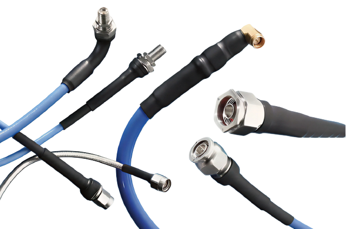
Know your connector
The connector sets the ceiling. It does not matter how good the cable is if the interface on the end of it runs out of bandwidth first — and unlike the cable, the connector also decides whether the joint is repeatable, which is what calibration depends on.
These are the six interfaces used across the range on this page, with the numbers that decide which one you need.
The fast one. A quarter turn locks it, which is why oscilloscopes and older analysers use it. That speed costs repeatability: the bayonet does not clamp the interface as precisely as a thread, so BNC is the wrong choice when you need the same match twice. Fine to 4 GHz, and there is a 75 Ω version that looks identical — check before you plug it into a 50 Ω port.
- Coupling
- Bayonet, quarter-turn
- Dielectric
- PTFE
- Mating torque
- Hand-tight — bayonet, no wrench
- Mates with
- BNC only
The standard instrument port across the Siglent bench range. Bigger than SMA, so it handles more power and survives far more connection cycles — standard types are good to 11 GHz, precision ones to 18 GHz. If your instrument has an N port, start here.
- Coupling
- Threaded, knurled or hex
- Dielectric
- PTFE (air in precision types)
- Mating torque
- 15–20 in-lb (1.7–2.3 N·m)
- Mates with
- N only
The device-side connector almost everything uses: filters, amplifiers, antennas, evaluation boards. It is a PTFE-filled connector, so it is the least precise of the small threaded family and it wears — treat SMA as a consumable on a busy bench, and torque it properly rather than nipping it up with pliers.
- Coupling
- Threaded
- Dielectric
- PTFE
- Mating torque
- 7–10 in-lb steel, 3–5 in-lb brass
- Mates with
- 3.5 mm, 2.92 mm
An air-dielectric precision connector — the same 3.5 mm you will see written as APC-3.5 (Amphenol Precision Connector). Because the dielectric is air rather than plastic, it is repeatable enough for calibration work, which is why 3.5 mm calibration kits exist and SMA ones largely do not.
- Coupling
- Threaded
- Dielectric
- Air
- Mating torque
- 7–10 in-lb (0.8–1.1 N·m)
- Mates with
- SMA, 2.92 mm
Also called the K connector. Same thread as SMA and 3.5 mm, but built precisely enough to stay mode-free to 40 GHz. This is the port on the SSA5000A analysers and the SSG5000A and SSG6000A generators.
- Coupling
- Threaded
- Dielectric
- Air
- Mating torque
- 7–10 in-lb (0.8–1.1 N·m)
- Mates with
- SMA, 3.5 mm
NMD stands for Network Measurement Division — the interface used on VNA test ports. The large threaded body takes the sideways and pulling forces of a heavy test cable and carries them into the instrument chassis instead of into the delicate 3.5 mm interface. On a VNA, where the cable stays connected all day and the port is the expensive part, that bracing is the whole point. The SNA5022A and SNA5032A use it.
- Coupling
- Threaded, large braced body
- Dielectric
- Air
- Mating torque
- 7–10 in-lb on the 3.5 mm interface
- Mates with
- A 3.5 mm interface, inside a bracing shell
Fits, and rated, are not the same thing
SMA, 3.5 mm and 2.92 mm share a thread, so any of them will screw onto any other and appear to work. Two things follow, and both cost money:
- The joint is only as good as the lesser half. Put an SMA on a 2.92 mm port and you have an SMA-grade connection — the 40 GHz rating stays in the datasheet, not in your setup.
- Mixed matings wear precision connectors. A PTFE-filled SMA mated repeatedly into an air-dielectric port will shorten that port’s life. Keep a port saver in between.
2.4 mm and 1.85 mm are a separate family. They mate with each other and with nothing else here. Forcing one onto an SMA or 3.5 mm connector damages both immediately and permanently — there is no partial fit and no recovery.
Which cable does my instrument need?
The RF port decides it. Every port below is taken from the instrument’s own datasheet — check yours before ordering, because the interfaces are not interchangeable.
| Instrument | Its RF port | Cable end you need | Cables that fit |
|---|---|---|---|
| SSA3000X · SSA3000X Plus · SSA3000X-R | N female | N male | N-BNC-2L, N-N-6L, N-SMA-6L, S06-NMSF-1M |
| SVA1000X | N female | N male | N-N-6L, N-SMA-6L, S06-NMSF-1M |
| SSG3000X · SSG5000X | N female | N male | N-N-6L / 18L, N-SMA-6L / 18L, S06/S18-NMSF-1M |
| SNA5002A · 5012A · 5004A · 5014A | Type-N female | N male | N-N-18L, N-SMA-18L, S18-NMSF-1M |
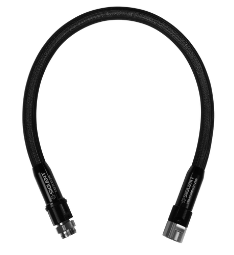
| SNA5022A · SNA5032A | 3.5 mm NMD male | NMD 3.5 mm female | V26-N35MN35F-25I, V26-N35FA35F-25I |
| SSA5000A | 2.92 mm male | 2.92 mm female | S40-29M29F-1M, 2.92F-2.92F-40A |
| SSG5000A · SSG6000A | 2.92 mm male | 2.92 mm female | S40-29M29F-1M, 2.92F-2.92F-40A |
A connector that fits is not the same as a connector that is rated. SMA, 3.5 mm and 2.92 mm all mate with each other mechanically, so a mismatched pair will screw together and appear to work — but the joint is limited to the lesser interface, and repeated mating of dissimilar connectors wears them. Match the interface when the frequency matters.
For N-port instruments
SSA3000X, SSA3000X Plus, SSA3000X-R, SVA1000X, SSG3000X, SSG5000X and the Type-N SNA5000A models.
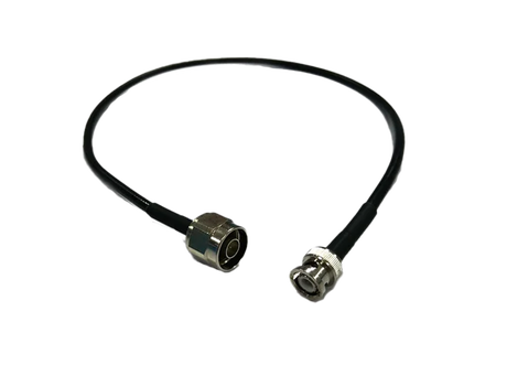
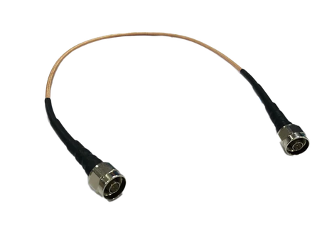
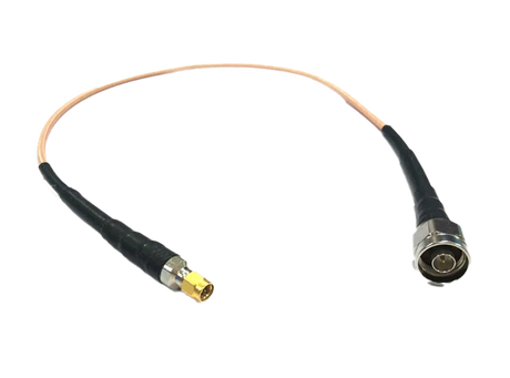
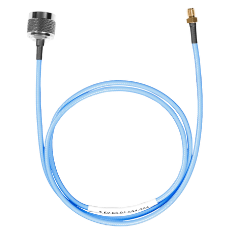
SMA female end — mates straight onto a male SMA device, no extra adaptor.
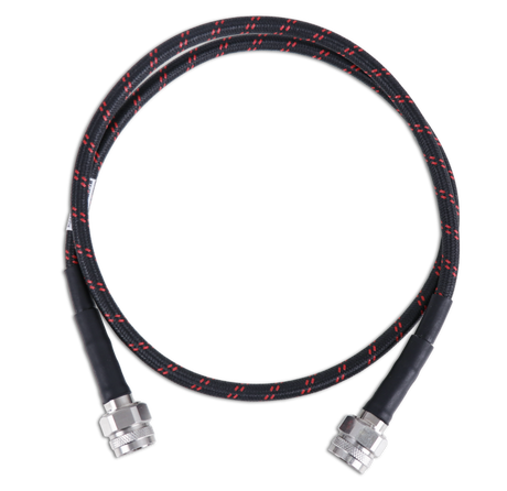
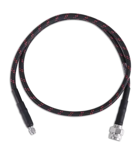
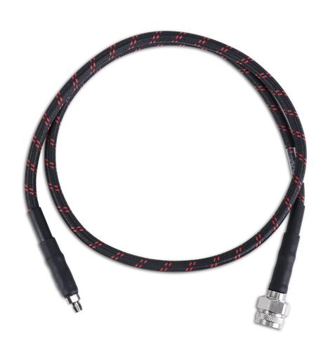
The 18 GHz version of the S06 — same ends, for N-port work above 6 GHz.
SMA to SMA
For SMA-terminated devices, filters, amplifiers and evaluation boards — and between SMA-ported instruments.
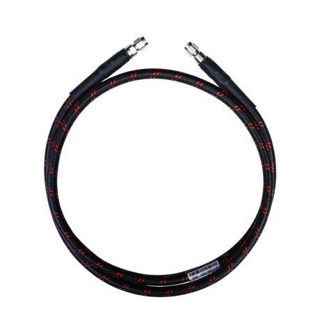
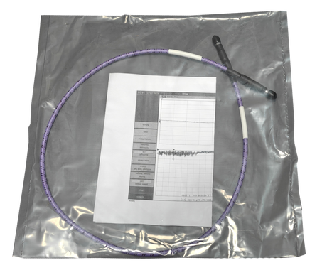
A low-loss assembly from our cable-assembly range rather than a Siglent part number — the budget route to the same connectors and bandwidth.
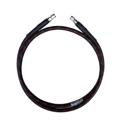
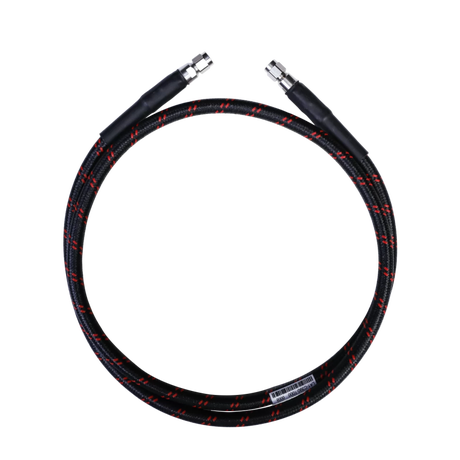
2.92 mm — to 40 GHz
The SSA5000A analysers and the SSG5000A and SSG6000A generators all present a 2.92 mm male RF port.
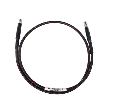
The female end mates with the 2.92 mm male port on the instrument.
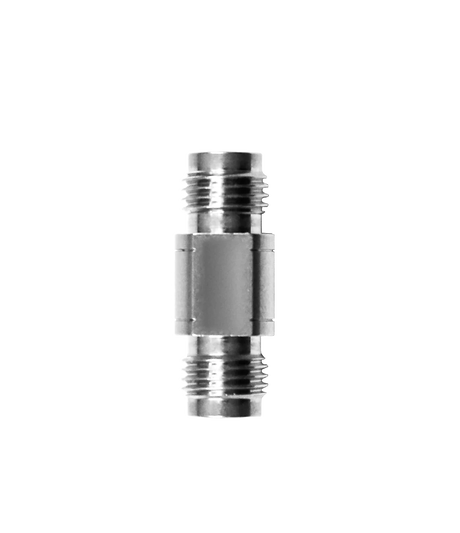
Joins two male-ended cables, and works as a port saver so the wear lands here instead of the instrument.
VNA test-port cables
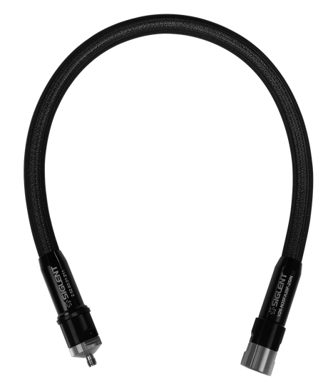
The SNA5022A and SNA5032A are the only instruments here with 3.5 mm NMD test ports — these two cables are what mates with them.
Utility kit
Cables, adaptors and an attenuator in one box.
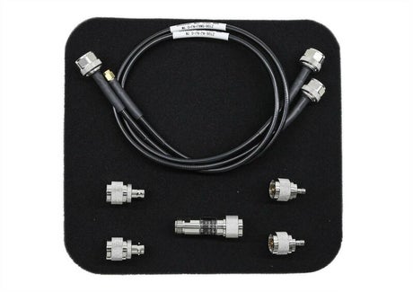
Everything needed to get an SSA3000X or SSA3000X Plus onto SMA and BNC devices in one box.
Six measurements, and the cable each one needs
Where the cable actually changes the answer — and what to use.
Measuring a filter or amplifier
The generator output drives the device, the RF input reads what comes back out, so the signal passes through two cables before it reaches the trace. Both sets of loss land on your result, which is why you normalise with the cables connected to each other first. Use a matched pair so the correction stays valid.
Receiver sensitivity and blocking
You are setting an absolute level at the receiver input, so cable loss directly offsets it. At −110 dBm an unaccounted 2 dB is the difference between a pass and a fail. Measure the loss of the exact lead you will use, at the frequency you will use, and correct for it.
S-parameters on a VNA
Here the cable is not an accessory, it is part of the instrument. Calibration moves the reference plane to the end of the cable, so everything the cable does is removed — until you move it. Bend it after calibrating and the phase shifts and the calibration decays. This is why VNA cables are phase-stable and use braced NMD test-port connectors.
Working at 40 GHz
Above about 26 GHz the connector stops being a detail. These instruments use a 2.92 mm port, an air-dielectric interface with tight tolerances, and a worn or wrongly-torqued connection shows up as ripple you will chase for hours. Fit a port saver on day one.
Antenna and feedline checks
Return loss and distance-to-fault look at reflections, so the test cable’s own reflections sit directly on top of the answer. A tired lead invents faults that are not in the feeder. Keep a known-good cable for this work and retire it when the numbers drift.
EMC pre-compliance and probing
You are hunting for emissions at very low levels, often right next to the noisy board that is producing them. If the cable’s shielding is poor it picks up the same field the probe is meant to be measuring, and you end up chasing a signal that entered through the lead.
Not sure which one you need?
Tell us the instrument and what you are connecting it to, and we will name the cable — including whether the one you already have is holding your measurement back. We are the official Siglent distributor for the European Union, so the answer comes from the same people who supply the instrument.
Need a length or connector pair that is not listed here? We build assemblies to spec as well — just ask.