

Logic probes (MSO)
Sixteen digital channels, captured and triggered on the same timebase as your analogue inputs. Two modules cover the range — and which one you need is decided entirely by which oscilloscope you own, not by preference.
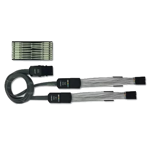
What a logic probe actually adds
An oscilloscope shows you a waveform. Most embedded faults are not in the waveform — they are in the relationship between a waveform and the bus traffic around it. A regulator that dips when a particular SPI transfer starts, a reset that asserts three clocks too early, an I²C device that NAKs only when a motor is running: none of these are visible on analogue channels alone, and none are visible on a logic analyser alone either, because the analogue behaviour is half the story.
A logic probe turns the oscilloscope into a mixed-signal instrument. Sixteen digital channels are sampled on the same timebase as the analogue ones, so a bus transaction and a supply rail sit on one screen with one trigger and one cursor set. You can trigger on a decoded I²C address and look at what the analogue channel did at that instant — the correlation is exact, because it is one acquisition rather than two instruments and a guess.
Both modules present 16 channels split into two threshold groups (D15–D8 and D7–D0), so a 3.3 V bus and a 5 V bus can be probed at once with the correct threshold on each. Presets cover TTL, CMOS, 3.3 V LVCMOS and 2.5 V LVCMOS, and a user-defined threshold is settable in 10 mV steps for anything unusual. Minimum detectable swing is 800 mVpp on both.
The difference between them is electrical margin and speed. The SPL2016 takes ±50 V peak, works over a ±20 V dynamic range, resolves a 3.3 ns pulse and accepts data up to 300 Mbps. The SLA1016 takes ±20 V peak, ±10 V dynamic range, 8.3 ns and 120 Mbps. In practice, though, the choice is made for you: each module fits a different set of oscilloscopes and they are not interchangeable. Check your model in the table below before ordering.
The models
2 products. Prices exclude VAT.
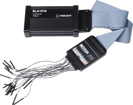
For the SDS1000X-E and SDS2000X-E 4-channel models, and all SDS800X HD and SDS1000X HD. 100 kΩ || 8 pF input, ±10 V dynamic range, 120 Mbps, 8.3 ns minimum pulse width. Supplied with the interface cable, flat and flying leads and grabber clips.
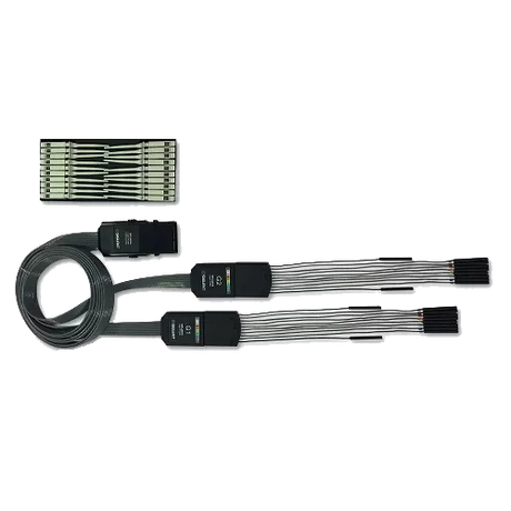
For the SDS2000X Plus, SDS2000X HD, SDS3000X HD, SDS5000X, SDS6000A, SDS6000L and SDS7000A. Higher margin and speed — 100 kΩ || 18 pF, ±20 V dynamic range, 300 Mbps and a 3.3 ns minimum pulse width.
Specifications side by side
Every model in this family, on one row each.
| Model | Fits these oscilloscopes | Input impedance | Dynamic range | Max input | Max data rate | Min pulse width | User threshold |
|---|---|---|---|---|---|---|---|
| SLA1016 | SDS1000X-E (4-ch) · SDS2000X-E (4-ch) SDS800X HD · SDS1000X HD | 100 kΩ || 8 pF | ±10 V | ±20 V peak | 120 Mbps | 8.3 ns | −8 V to +8 V |
| SPL2016 | SDS2000X Plus · SDS2000X HD · SDS3000X HD SDS5000X · SDS6000A · SDS6000L · SDS7000A | 100 kΩ || 18 pF | ±20 V | ±50 V peak | 300 Mbps | 3.3 ns | −10 V to +10 V |
What people use the digital channels for
Decoding a bus
I²C, SPI, UART, CAN and LIN decode straight from the digital channels, so the traffic appears as readable values rather than edges you have to count.
Correlating analogue with digital
See what a supply rail does at the exact moment a chip-select goes low. One acquisition, one timebase, no guessing about alignment.
Triggering on a rare condition
Arm on a specific bus pattern or address and catch the one transaction in a million that misbehaves, with the analogue context captured alongside it.
Checking timing against the datasheet
Setup and hold, reset sequencing, clock-to-output. Sixteen channels is usually enough to see a whole interface at once.
Questions we are asked
Which module fits my oscilloscope?
The SLA1016 fits the 4-channel SDS1000X-E and SDS2000X-E models and every SDS800X HD and SDS1000X HD. The SPL2016 fits the SDS2000X Plus, SDS2000X HD, SDS3000X HD, SDS5000X, SDS6000A, SDS6000L and SDS7000A. They are not interchangeable — check the table above, and note that 2-channel versions of the X-E series have no digital input at all.
What sample rate and memory depth do I get?
Those are set by the oscilloscope, not by the probe — which is why you will see different figures quoted in different places. The probe defines the electrical interface: impedance, thresholds, maximum data rate and minimum pulse width. Check the digital-channel specification of your own oscilloscope model for the sampling figures.
Do I need a separate software licence?
On current firmware the logic function is normally included for the supported series. Historically some SDS1000X-E units needed a separate 16LA licence. Update the oscilloscope to the latest firmware first — that resolves it in most cases.
Can I probe a 5 V bus and a 3.3 V bus at the same time?
Yes. The channels are split into two independent threshold groups, D15–D8 and D7–D0, so each group can carry its own threshold. Use a preset or set a custom value in 10 mV steps.
What is the smallest signal these can see?
Both need at least 800 mVpp of swing. Below that the threshold comparator cannot reliably resolve a level, and you should be looking at the signal on an analogue channel anyway.
Does the SLA1016 need its own firmware?
It has firmware of its own, separate from the oscilloscope's. Support for the SDS800X HD and SDS1000X HD arrived in SLA1016 firmware v8.2.3. If yours is older than v8.1.16 it must be updated in stages — see the SLA1016 product page for the procedure before upgrading your scope.
Not sure which one fits your measurement?
Tell us the instrument, the signal and what you are trying to see. We are the official Siglent distributor for the EU and we will point you at the right part — including when the right answer is a probe from another family, or nothing at all.