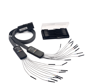
Siglent SPL2016 16 Channel logic probe module
The Siglent SPL2016 Logic Probe Module probe set for Siglent's affordable entry-to-mid-range 4-channel oscilloscopes — adds 16 digital channels so you can view, trigger and decode digital buses alongside the analog signals (MSO).
Compatibility — supported oscilloscopes
The SPL2016 is designed for specific scope families. It is not interchangeable with the other logic probe — make sure your model is in the supported list below.
- SDS2000X Plus
- SDS2000X HD
- SDS3000X HD
- SDS5000X
- SDS6000A
- SDS6000L
- SDS7000A
- Update the oscilloscope to the latest firmware — recent versions include the logic (16LA) license by default or make activation straightforward.
- The probe set provides the physical hardware; the scope enables the MSO function via a software option (now usually included).
- Firmware sensitivity is low — simply run the latest scope firmware.
Support can change with firmware updates — always verify your exact model and its current firmware on Siglent's official firmware download page before ordering, or contact us with your model number.
Installation & setup
The SPL2016 is plug-and-play: it connects to the dedicated MSO digital port on your oscilloscope and the digital channels are enabled in firmware — no staged firmware procedure is required.
Step by step
- 1Power on your oscilloscope and confirm it runs a recent firmware version (the logic / 16LA function is included in current firmware for the supported series).
- 2Plug the SPL2016 module into the oscilloscope's digital (MSO) input connector.
- 3Connect the flying leads to your signals and at least one ground lead to circuit ground; use the micro-clips on small test points.
- 4Press the Digital button on the scope to turn on the 16 channels, then set the threshold per pod (TTL / CMOS / LVCMOS or a custom value).
- 5Add bus decoding (I²C, SPI, UART, CAN, LIN…) and digital triggering from the scope menus to debug analog and digital together.
Specifications
| Channels | 16 digital (D0–D15) |
| Input impedance | 100 kΩ || 8 pF |
| Max. input voltage | ±50 V peak |
| Input dynamic range | ±20 V |
| Min. input voltage swing | 800 mVpp |
| Threshold groupings | Pod 2: D15–D8 · Pod 1: D7–D0 |
| Threshold selections | TTL (1.5 V), CMOS (2.5 V), 3.3 V LVCMOS (1.65 V), 2.5 V LVCMOS (1.25 V) |
| User-defined threshold | ±3 V in 10 mV steps |
| Threshold accuracy | ±(3% × threshold + 200 mV) |
| Max. input frequency | Probe: 150 MHz · Line: 50 MHz |
| Min. detectable pulse width | 3.3 ns |
| Channel skew | ±(1 digital sample interval) |
| Max. sample rate | up to 500 MSa/s (set by oscilloscope) |
| Record length | up to 50 Mpts (set by oscilloscope) |
Specifications summarised from the oscilloscope datasheet; see the datasheet for full, guaranteed specifications.
In the box
- SPL2016 logic probe module — with integrated wiring harness
- 16× flying leads — one digital probe wire per channel (D0–D15)
- 2× ground leads
- 20× probe clips — micro-grabber clips
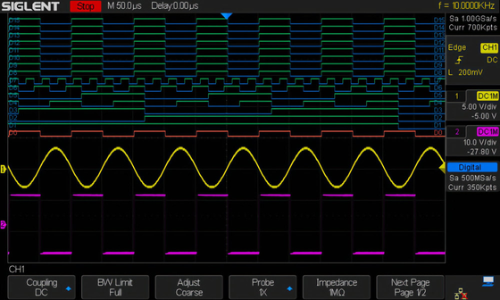
With the SPL2016 fitted and the MSO option enabled, your scope shows 16 timed digital channels alongside the analog traces — ideal for embedded debug and decoding I²C, SPI, UART, CAN, LIN and more in step with the analog behaviour.
Add MSO to your oscilloscope
Order the SPL2016, or tell us your scope model and we'll confirm the right logic probe and firmware.