

Double-pulse testing of SiC, GaN, MOSFET & IGBT devices
The standard dynamic test for power semiconductors: what double-pulse testing measures, why wide-bandgap devices make it hard, and the Siglent solution stack that automates it.
Double-pulse testing (DPT) is the core method for evaluating the dynamic behaviour of power switches — MOSFETs, IGBTs and the new wide-bandgap SiC and GaN devices driving EV inverters, chargers and solar converters. Two gate pulses through an inductive load reveal switching energies, timing and diode reverse recovery at precisely controlled current.
Why it's demanding
- Speed: SiC and GaN switching transitions are in the nanosecond range, with edges of only a few ns — you need 500 MHz+ of clean bandwidth or the switching losses are simply wrong
- Common-mode interference: on an 800 V bus the common-mode swing reaches kilovolts; ordinary differential probes lose CMRR at high frequency and paint false oscillations onto VGS
- Data volume: dozens of parameters (Eon, Eoff, tr, tf, dv/dt, di/dt, Qrr where it applies…) per device corner — manual analysis is slow and error-prone
What you are measuring depends on the technology, and Qrr is the clearest case. A silicon MOSFET or IGBT has a p-n body diode that stores minority carriers, so reverse recovery is real and often dominates turn-on loss. A SiC MOSFET has a body diode too, with a much smaller Qrr. An enhancement-mode GaN HEMT has no body diode at all — it is a lateral device with no p-n junction, so it stores no minority charge and Qrr is zero. It still conducts in reverse, through the 2DEG channel in third-quadrant operation, at a forward drop set by the gate voltage. What you do still have to account for on GaN is the charge and discharge of the output capacitance Coss, so plan the measurement around dv/dt and displacement current rather than around a recovery peak that does not exist.
The Siglent solution stack
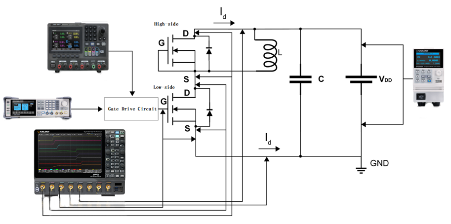
- SDS5000X HD / SDS3000X HD 12-bit oscilloscope — high resolution keeps both the kV-scale drain voltage and the mV-scale details honest
- ODP6000B optical-isolated probes — 160 dB CMRR via fibre-optic isolation for gate-source measurements on the high side
- Current measurement via shunt or CP-series current probe
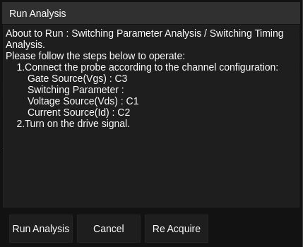
- Siglent DPT software — sequences the pulses, auto-identifies the switching regions, extracts the full parameter table and exports an HTML/XML report
What you get
- Switching parameters: Eon, Eoff, Vpeak, Ipeak
- Timing: td(on), td(off), rise and fall times
- Diode reverse recovery and capacitance analysis
- A generated report with screenshots and tables — the factory quotes an efficiency gain of 80 % versus manual processing
The result is a repeatable, documented dynamic characterisation of every device corner — the data you need for gate-resistor tuning, loss budgets and datasheet verification.
Instruments used in this note
12-bit HD series recommended for DPT
500 MHz, 160 dB CMRR — €4,500
CP-series clamp probes to 750 A
Related application notes
Our engineers use these instruments daily — ask us anything.