

Siglent ODP6050B 500 MHz Optical Isolated Voltage Probe


Siglent ODP6050B is a 500 MHz optical isolated voltage probe with ±60 kV isolation and ultra-high CMRR. Ideal for accurate high-voltage floating and gate signal measurements in Si, SiC, and GaN power designs. Features battery operation, auto-zeroing, and multiple attenuators for flexible test setups.
Measuring a signal that is floating at thousands of volts
The hard measurement in a half-bridge is the high-side gate. The signal you want is a few volts of gate drive. The node it sits on is slewing through hundreds of volts in a few nanoseconds. An ordinary probe sees both, and the common-mode transient swamps the few volts you came for.
The ODP6050B breaks the electrical connection entirely. The front end sits on the circuit, runs from its own battery, converts the signal to light and sends it down two metres of optical fibre to a receiver plugged into the oscilloscope. There is no copper between the device under test and the instrument, so there is no path for the common-mode current that causes the problem.
That gives 500 MHz of bandwidth, a 0.7 ns typical rise time and ±60 kV of isolation. It is the probe for gate-drive work on fast Si, SiC and GaN devices — and, as the two sections below set out honestly, it is a probe whose real performance depends entirely on which attenuator you fit.
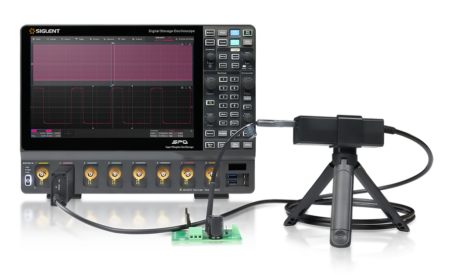
Three parts, and no copper between them
Power over fibre and an optical signal path give complete galvanic isolation between the measurement system and the device under test.
Front end (E/O transmitter)
Takes the attenuator on an SMA input, runs from a replaceable lithium battery, and converts the differential voltage to an optical signal. 102 × 45 × 33 mm, and it sits on the circuit at whatever potential the circuit is at.
Optical fibre
Two metres of fibre, and the only thing joining the two halves. This is where the isolation comes from — light carries the signal, so no current can follow it. Keep the bend radius above 10 cm.
Rear end (O/E receiver)
Plugs directly into an oscilloscope BNC and takes USB 5 V / 2 A. Carries the auto-zero button and the status indicator. Presents a 50 Ω terminated output at ±0.5 V full scale.
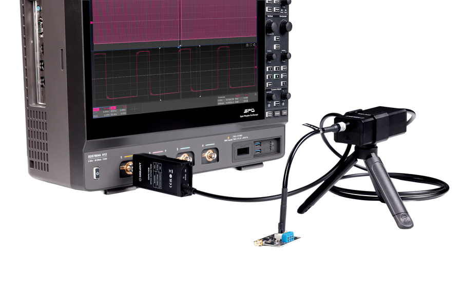
Why this probe exists now and did not ten years ago
Wide-bandgap devices moved the goalposts. Silicon and IGBT designs switch in around a hundred nanoseconds, and a 100 MHz differential probe resolves that comfortably. Silicon carbide is an order of magnitude faster, gallium nitride another, and the rail voltages went up at the same time rather than down.
Faster edges need bandwidth, and higher rails need common-mode rejection at that bandwidth — which is the part that gets quietly dropped. A probe’s CMRR headline is almost always its DC figure, and DC is not where a GaN half-bridge does its damage.
That combination — nanosecond edges sitting on kilovolt nodes — is what optical isolation was built for, and it is the honest boundary of when this probe is worth its price.
How fast, and how high
| Device | Rise time | Differential voltage |
|---|---|---|
| Silicon / IGBT | ~100 ns | up to ~700 V |
| SiC | ~10 ns | up to ~3.3 kV |
| GaN | 1 ns and below | up to ~10 kV |
Indicative trend across device technologies, from Siglent’s ODP6000B technical material — not a specification for any particular part.
Read this before you order: voltage and bandwidth trade against each other
The ODP6050B is a 500 MHz probe and it will measure up to ±5000 Vpk. It will not do both at once. The maximum test voltage falls as the test frequency rises, and the figures are not close — at full voltage you have 700 kHz, not 500 MHz.
| Maximum test voltage | Maximum test frequency | Attenuator |
|---|---|---|
| ±5000 Vpk | 700 kHz | 10000X |
| ±2500 Vpk | 800 kHz | 5000X |
| ±1000 Vpk | 2 MHz | 2000X |
| ±500 Vpk | 3 MHz | 1000X |
| ±250 Vpk | 20 MHz | 500X |
| ±100 Vpk | 50 MHz | 200X |
| ±50 Vpk | 100 MHz | 100X |
| ±25 Vpk | 200 MHz | 50X |
Source: ODP6000B series instruction manual, EN01D. If your work is high voltage and high frequency, that is the specification to design your test around — not the headline bandwidth.
CMRR is not one number — it depends on the attenuator
Siglent publish 160 dB (DC–10 MHz), and that is a real figure — roughly a hundred million to one. But it belongs to a low-ratio attenuator at low frequency. Every attenuator starts near 180 dB at DC and falls as frequency rises, and the high-voltage attenuators fall fastest. This is the trade-off that decides whether the probe will actually solve your problem.
| Attenuator | DC | 1 MHz | 10 MHz | 100 MHz |
|---|---|---|---|---|
| 5:1 | ~180 | ~168 | ~150 | ~130 |
| 50:1 SUPPLIED | ~180 | ~150 | ~125 | ~100 |
| 200:1 | ~180 | ~135 | ~115 | ~85 |
| 1000:1 SUPPLIED | ~180 | ~100 | ~85 | ~55 |
| 2000:1 SUPPLIED | ~180 | ~90 | ~80 | ~50 |
| 5000:1 SUPPLIED | ~180 | ~85 | ~75 | ~45 |
| 10000:1 | ~180 | ~80 | ~70 | ~40 |
Values in dB, read from the CMRR curves in the ODP6000B instruction manual and rounded to the nearest 5 dB — Siglent publish them as a graph rather than a table, so treat them as indicative, not guaranteed. Rows marked SUPPLIED are the four attenuators that ship with the probe.
The practical rule: fit the lowest attenuation ratio that safely covers your signal. Going up a ratio to gain headroom you do not need costs common-mode rejection, bandwidth and resolution all at once — and common-mode rejection is the reason you bought an optical probe.
We wrote that up properly: optically isolated probes and high-CMRR measurement turns these decibels into volts, adds the voltage-versus-frequency limit, and gives a five-step procedure for picking the attenuator with a worked example.
What common-mode rejection is worth, in volts
CMRR is quoted in decibels, which makes it easy to nod at and hard to feel. Convert it to volts and it stops being abstract. Take the measurement this probe exists for — the high-side gate of a half-bridge running from a 600 V rail, where the gate signal itself is about 15 V.
A classical high-voltage differential probe has roughly 25 dB of common-mode rejection at 100 MHz. That is a ratio of about 18:1. So 600 V of common mode arrives at the screen as 600 ÷ 18 ≈ 33 V of error — on a signal that is only 15 V tall. The error is more than twice the thing you are measuring, and nothing about the trace tells you which part is which.
| Common-mode voltage | 600 V |
| Differential signal | 15 V |
| Classic HV differential probe, 100 MHz | 25 dB ≈ 18:1 |
| Error it contributes | ≈ 33 V |
| ODP6050B, 50X tip, 100 MHz | ≈ 100 dB |
The 25 dB figure is from Wolfspeed’s application note Dynamic Characterization and Measurement Methods, quoted by Siglent. The ODP6050B row is read from the manual’s CMRR curves.
The attenuator is the range
The probe amplifier itself takes ±0.5 V. Every measurement range in the table below is simply that figure multiplied by the attenuation ratio, which is why the specification sheet’s “±25 V” is the 50X number rather than a limit on the probe. Four attenuators are supplied — 50X, 1000X, 2000X and 5000X. The other seven are ordered separately.
| Model | Ratio | Measurement range | Max non-destructive | Input impedance | Connector | Price ex VAT |
|---|---|---|---|---|---|---|
| CK-AT5X-2-SMA | 5:1 | ±2.5 Vpk | 2 kVpp | 1 MΩ ‖ 28 pF | MMCX | €173 |
| CK-AT10X-2-SMA | 10:1 | ±5 Vpk | 2 kVpp | 1 MΩ ‖ 6 pF | MMCX | €173 |
| CK-AT20X-2-SMA | 20:1 | ±10 Vpk | 2 kVpp | 5 MΩ ‖ 6 pF | MMCX | €173 |
| CK-AT50X-2-SMA | 50:1 | ±25 Vpk | 2 kVpp | 10 MΩ ‖ 4 pF | MMCX | supplied |
| CK-AT100X-2-SMA | 100:1 | ±50 Vpk | 3 kVpp | 10 MΩ ‖ 2 pF | MMCX | €173 |
| CK-AT200X-2-SMA | 200:1 | ±100 Vpk | 3 kVpp | 10 MΩ ‖ 2 pF | MMCX | €173 |
| CK-AT500X-2-SMA | 500:1 | ±250 Vpk | 5 kVpp | 10 MΩ ‖ 2 pF | HVMCX | €288 |
| CK-AT1000X-2-SMA | 1000:1 | ±500 Vpk | 5 kVpp | 20 MΩ ‖ 2 pF | HVMCX | supplied |
| CK-AT2000X-2-SMA | 2000:1 | ±1000 Vpk | 6 kVpp | 20 MΩ ‖ 2 pF | HVMCX | supplied |
| CK-AT5000X-2-SMA | 5000:1 | ±2500 Vpk | 6 kVpp | 40 MΩ ‖ 2 pF | HVMCX | supplied |
| CK-AT10000X-2-SMA | 10000:1 | ±5000 Vpk | 12 kVpp | 40 MΩ ‖ 2 pF | 5.08 mm socket | €368 |
Prices from Siglent’s Annex 1 price list 2026_1, ex VAT. The optional attenuators do not yet have their own pages on this shop — ask us for a quotation and we will order them with the probe. Note 2 of the manual: where an MMCX connector is specified, SSMB may be used instead. There is a step-by-step method for choosing between them in our application note on high-CMRR measurement.
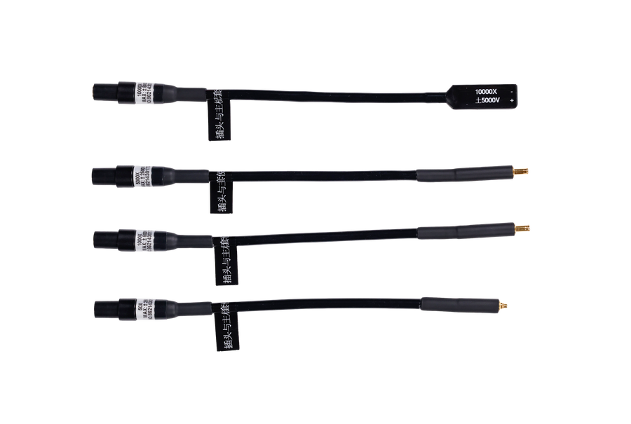
Specifications
| Bandwidth (−3 dB) | 500 MHz |
| Rise time (typical) | 0.7 ns |
| Terminal load | 50 Ω |
| Output voltage range | ±0.5 V |
| Host noise (Vrms, typical) | 1.5 mV |
| DC accuracy | ≤ ±1 % |
| Isolation voltage (DC + peak AC) | ±60 kV |
| Attenuator (50X) + host delay | 15.3 ns, with the 2 m optical fibre |
| Power — front end | Battery, approx. 8 hours operating, approx. 30 days standby |
| Power — rear end | USB 5 V / 2 A |
| Auto calibration | Yes, one button on the receiver |
| Operating temperature | −10 °C to 60 °C |
| E/O transmitter (front end) | approx. 102 × 45 × 33 mm |
| O/E receiver (rear end) | approx. 106 × 49 × 23 mm |
| Attenuator length | approx. 200 mm |
| Optical fibre length | approx. 2 m |
| Weight | approx. 400 g |
ODP6050B or ODP6100B?
Bandwidth and rise time are the only differences. Isolation voltage, the attenuator set, CMRR behaviour, the power arrangement and the contents of the case are identical on both.
| ODP6050B | ODP6100B | |
|---|---|---|
| Bandwidth | 500 MHz | 1 GHz |
| Rise time (typ.) | 0.7 ns | 0.45 ns |
| Isolation | ±60 kV | ±60 kV |
When a differential probe is the better buy
Optical isolation is expensive, and it is not always what the measurement needs. Below roughly 400 MHz, with moderate common-mode voltage, a high-voltage differential probe measures the same signal for a fraction of the cost. Siglent’s own DPB6150 pair reaches ±1500 Vpk with more than 80 dB of CMRR at DC.
Where the optical probe earns its price is common-mode rejection at high frequency — the fast switching edges of SiC and GaN devices, where a differential probe’s CMRR has already fallen away.
Manual & documentation
Both links go to Siglent’s own document server and always fetch the current revision, so they cannot go stale. Nothing opens in a new window.
Application note — optically isolated probes and high-CMRR measurement
siglent.eu · 16 min read
Written by us, and the practical companion to this page: what common-mode rejection is worth in volts, the CMRR curves tabulated by attenuator, the voltage-versus-frequency limit drawn as a boundary, a five-step attenuator selection procedure with a worked example, and the setup mistakes that quietly corrupt the result.
ODP6000B Series Instruction Manual
PDF · approx. 1.0 MB · EN01D
The complete specification: electrical and mechanical tables, all eleven attenuators with their measurement ranges and non-destructive limits, the CMRR curves, the maximum-voltage-versus-frequency table, the packing list and the fibre handling rules. Every figure on this page is read from it. It covers both models in the series.
Siglent’s application note — optical isolated probes and high CMRR
PDF · approx. 1.0 MB · factory original
The manufacturer’s own note, and the source of the differential-probe comparison. Worth reading for its side-by-side captures of the same gate edge measured with an optical probe and with a conventional differential probe.
There is no separate datasheet
Siglent publish one document for the ODP6000B series, and it is the instruction manual. There is no standalone datasheet — we checked the factory’s full document index and its own product page. That is not a problem in practice, because the manual carries everything a datasheet would: the electrical and mechanical specification tables, the complete attenuator list, the CMRR curves and the voltage-versus-frequency limits. If you were looking for a datasheet, the manual is it.
Firmware and documents for the oscilloscope you will use this probe with are on our downloads page, which is searchable by model number. If you need something we have not listed, just ask.
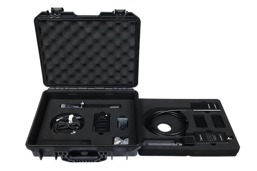
In the box
The full packing list from the instruction manual. Two batteries and a twin charger mean one pack charges while the other works, which is the point of a battery-powered front end.
| Voltage probe unit | 1 | E/O transmitter, 2 m fibre and O/E receiver |
| CK-AT50X-2-SMA | 1 | 50X attenuator — ±25 Vpk |
| CK-AT1000X-2-SMA | 1 | 1000X attenuator — ±500 Vpk |
| CK-AT2000X-2-SMA | 1 | 2000X attenuator — ±1000 Vpk |
| CK-AT5000X-2-SMA | 1 | 5000X attenuator — ±2500 Vpk |
| CK-327 | 2 | MMCX to Dupont cable |
| CK-28 | 5 | MMCX-K |
| CK-24 | 9 | HVMCX-K |
| CK-326 | 3 | HVMCX extension cable |
| CK-328 | 2 | MMCX to RG178 |
| CK-325 | 1 | Output extension cable |
| CK-314A | 1 | USB Type-C power cable, 1.5 m |
| CK-605 | 2 | Power supply adaptor, 5 V / 2 A |
| CK-690B | 1 | E/O transmitter support bracket |
| CK-691 | 1 | Battery charger set |
| Documents | — | Instruction manual, warranty card, test report |
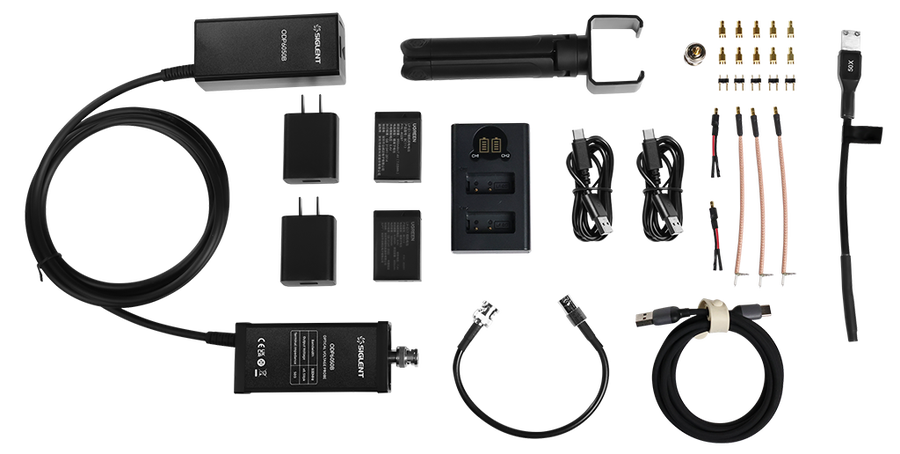
Using it properly
Six things from the instruction manual that decide whether the measurement is right — and whether the probe survives.
Set the scope to 50 Ω
Whenever the measured signal’s rise time is under 3.5 ns, set the oscilloscope input to 50 Ω and set the channel’s attenuation ratio to match the attenuator fitted. Get either wrong and the amplitude on screen is wrong.
Zero it in place
One press of the auto-zero button calibrates and zeroes the probe in about 20 seconds, without disconnecting it from the circuit. Green flashing means it is working; three beeps and steady green mean it succeeded.
Two batteries, user-replaceable
Standard card-type camera lithium cells, about 8 hours per charge and 30 days of standby. When they age you buy replacements yourself — no return to the factory. ⚠ Remove the attenuator first: fitted, it mechanically blocks the battery door.
It sleeps by itself
The transmitter wakes when the receiver is powered up and sleeps five seconds after the receiver is switched off, so battery is not wasted between measurements.
Respect the fibre
Minimum bend radius 10 cm. No knots, no twisting, nothing heavy resting on it, and inspect it before each use. The fibre is the isolation — if it fails, the probe does.
Power down before unplugging
The front end connects directly to high voltage on the device under test. Always switch the circuit off before removing the probe, and keep the transmitter box suspended and away from high-voltage pulse circuitry while measuring.
What it is used for
High-side gate drive in half- and full-bridge inverters
The measurement the probe exists for. VGS on the high-side device is a small differential signal riding on a node that swings the full DC link in nanoseconds.
Si, SiC and GaN device characterisation
Double-pulse testing of wide-bandgap devices, where the switching edge carries the information and a 100 MHz differential probe rounds it away.
Floating measurements under fast common-mode transients
Anywhere the reference point moves — motor drives, frequency converters, renewable-energy inverters.
Switching supplies, LED drivers and inverter appliances
R&D, debugging and maintenance across power electronics generally, including small differential signals sitting on large common-mode voltages.
Questions
What is the maximum voltage the ODP6050B can measure?
±5000 Vpk, with the optional CK-AT10000X-2-SMA attenuator fitted — but only up to 700 kHz. The maximum test voltage falls as frequency rises: ±2500 Vpk to 800 kHz, ±500 Vpk to 3 MHz, ±50 Vpk to 100 MHz and ±25 Vpk to 200 MHz. The four attenuators supplied with the probe cover ±25 V to ±2500 Vpk.
Can I get 500 MHz bandwidth and high voltage at the same time?
No, and this is the single most important thing to understand before ordering. The 500 MHz figure is the probe’s own bandwidth. What you actually get depends on the attenuator fitted, and the high-voltage attenuators are limited to a few hundred kilohertz or a few megahertz. Full bandwidth is a low-voltage measurement.
What does the ±60 kV isolation voltage mean?
It is the common-mode voltage the optical link will stand off — the potential the probe tip may float at relative to the oscilloscope’s ground. It is not the signal you are measuring. The differential signal is set by the attenuator, the isolation figure is what makes it safe to make that measurement on a floating node.
Is the 160 dB CMRR figure available on every range?
No. Every attenuator starts near 180 dB at DC, but CMRR falls with both frequency and attenuation ratio, and the high-voltage attenuators fall fastest. Reading the manual’s curves, the 50X tip is around 100 dB at 100 MHz while the 5000X tip is around 45 dB there. Choose the lowest ratio that safely covers your signal.
How is it powered, and how long does it run?
The front end runs from a replaceable lithium battery for about 8 hours, with roughly 30 days of standby. Two batteries and a twin charger are supplied, so one charges while the other works. The receiver at the oscilloscope end takes USB 5 V / 2 A.
Do I need to set anything on the oscilloscope?
Set the channel’s attenuation ratio to match the attenuator fitted, and set the input impedance to 50 Ω whenever the signal’s rise time is under 3.5 ns — the probe’s output is a 50 Ω terminated source.
How do I zero it?
Press the auto-zero button on the receiver. Calibration takes about 20 seconds and can be done without disconnecting the probe from the circuit. The indicator flashes green during calibration and beeps three times when it succeeds.
Should I buy this or a high-voltage differential probe?
If your measurement is below about 400 MHz and your common-mode voltage is moderate, a DPB6150A or DPB6150D differential probe does the job for a fraction of the price. The optical probe earns its cost when you need genuine common-mode rejection at high frequency — high-side gate drive on a fast SiC or GaN half-bridge is the case it was built for.
Where is the datasheet?
There isn’t one. Siglent publish a single document for the ODP6000B series — the instruction manual — and it carries everything a datasheet would: the full electrical and mechanical specifications, all eleven attenuators, the CMRR curves and the voltage-versus-frequency limits. It is linked in the documentation section above, along with the application note on high-CMRR measurement.
What is the difference between the ODP6050B and the ODP6100B?
Bandwidth and rise time only. The ODP6050B is 500 MHz with a 0.7 ns typical rise time; the ODP6100B is 1 GHz with 0.45 ns. Isolation voltage, attenuators, CMRR behaviour, power arrangement and everything in the box are identical.
Not sure which attenuator you need?
Tell us the voltage you are measuring and the frequency you need to see it at, and we will tell you which attenuator that combination actually allows — or say plainly if a differential probe would serve you better for a fraction of the cost. We are the official Siglent distributor for the European Union and we ship from the Netherlands.