

SSG6089A
A single coaxial output from 100 kHz to 67 GHz with 0.001 Hz resolution, −135 dBc/Hz phase noise at 1 GHz and a specified +10 dBm at 67 GHz. The top model of the SSG6000A family covers Ka-, Q-, U- and most of V-band without an external frequency extender.
At 67 GHz the right configuration depends on the application, and two of the options are fitted at the factory. So instead of a fixed webshop price we prepare a personal offer: you tell us about your application, and we work out the configuration that fits it with the Siglent factory. The 13.6, 20 and 40 GHz models of the family are available directly in the webshop.
The model you have in mind, the options, the quantity and what you want to measure. The form at the bottom of this page takes two minutes.
We review your application together with the Siglent factory and make sure the instrument and its options fit what you want to do.
By e-mail, with the price, the delivery time and the warranty terms for your configuration. There is no obligation until you accept it.
100 kHz to 67 GHz from one connector
The SSG6089A is the 67 GHz model of Siglent’s SSG6000A microwave generators. It delivers a continuous sweep from 100 kHz to 67 GHz at a single 1.85 mm output, so one instrument serves the baseband, the intermediate frequency and the millimetre-wave carrier of the same design.
A standard OCXO reference holds the frequency to ±1 ppb over temperature. The level is set in 0.01 dB steps between −110 dBm and +24 dBm, with a specified +10 dBm still available at 67 GHz. AM, FM and phase modulation are standard; pulse modulation with more than 80 dBc on/off ratio and a 2,047-pulse train generator are options.

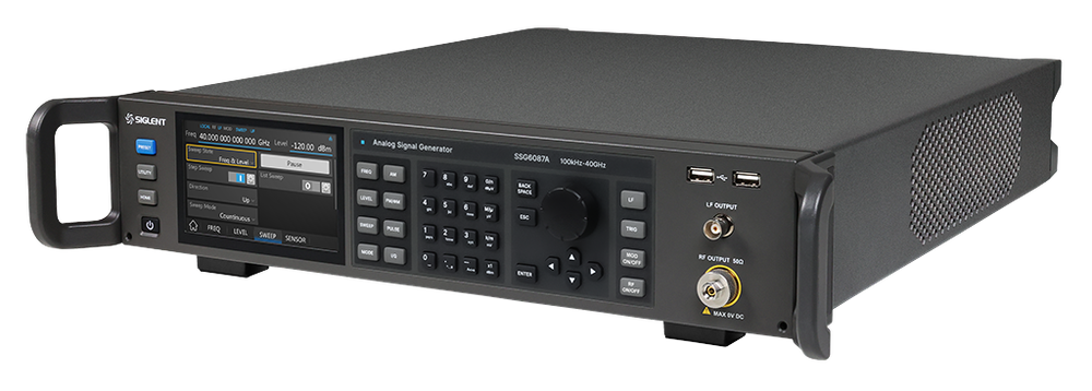
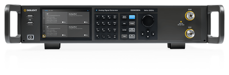
The photographs show the SSG6000A housing with the 40 GHz front panel. The SSG6089A has the same panel with a 1.85 mm RF output and a 100 kHz – 67 GHz label.
Key highlights
67 GHz without an extender
One coaxial source for Ka-, Q-, U- and most of V-band. No banded multiplier, no waveguide transition in the path.
Phase noise to −149 dBc/Hz
−135 dBc/Hz at 1 GHz, 10 kHz as delivered; −149 dBc/Hz (typ.) with the factory option LPH2.
+10 dBm at 67 GHz
Specified output power, enough for many mixer LO ports, with a level error of 0.7 dB or less in the working range.
Pulses for radar work
Pulse modulation above 80 dBc on/off with edges under 15 ns, and pulse trains of up to 2,047 pulses, as options.
Output power, band by band
At millimetre-wave frequencies every decibel of cable and adapter loss counts, so the usable power at the connector decides whether you need an external amplifier. The chart shows the maximum output power Siglent specifies, with and without the high-power option.
Specified maximum output power of the SSG6089A (data sheet EN03A). Standard configuration in blue, with the factory-fitted option SSG6080A-HP40 in orange. Above 40 GHz both lines coincide.
| Carrier | Standard | With HP40 |
|---|---|---|
| 3 MHz to 3.4 GHz | +18 dBm | +24 dBm |
| 6 to 9 GHz | +17 dBm | +23 dBm |
| 18.5 to 26 GHz | +12 dBm | +19 dBm |
| 26 to 36 GHz | +10 dBm | +18 dBm |
| 36 to 40 GHz | +9 dBm | +16 dBm |
| 40 to 45 GHz | +18 dBm | +18 dBm |
| 45 to 50 GHz | +15 dBm | +15 dBm |
| 50 to 67 GHz | +10 dBm | +10 dBm |
Selected bands; the full table from 9 kHz is in the data sheet.
Between 5 and 9 dB more specified power from 3 MHz to 40 GHz, and a level setting range up to +30 dBm below 4 GHz. Above 40 GHz the specified maximum is the same with and without the option: do not order HP40 for a 60 GHz task.
From 50 to 67 GHz the source delivers a specified +10 dBm, and +18 dBm from 40 to 45 GHz. That is enough for many mixer and multiplier inputs without a separate amplifier in the path.
Level error ≤ 0.7 dB between +10 and −20 dBm up to 67 GHz (ALC on, 20 to 30 °C). A USB power sensor such as the R&S NRP67S closes the loop at the end of your cable and corrects its loss.
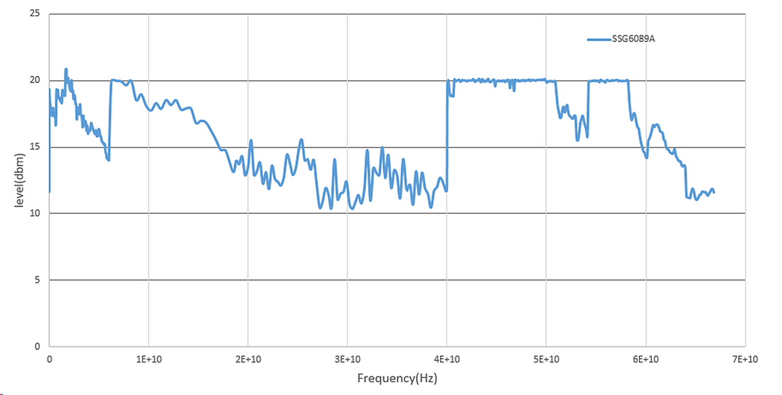
Measured maximum power, standard configuration (data sheet EN03A, not a guaranteed specification).
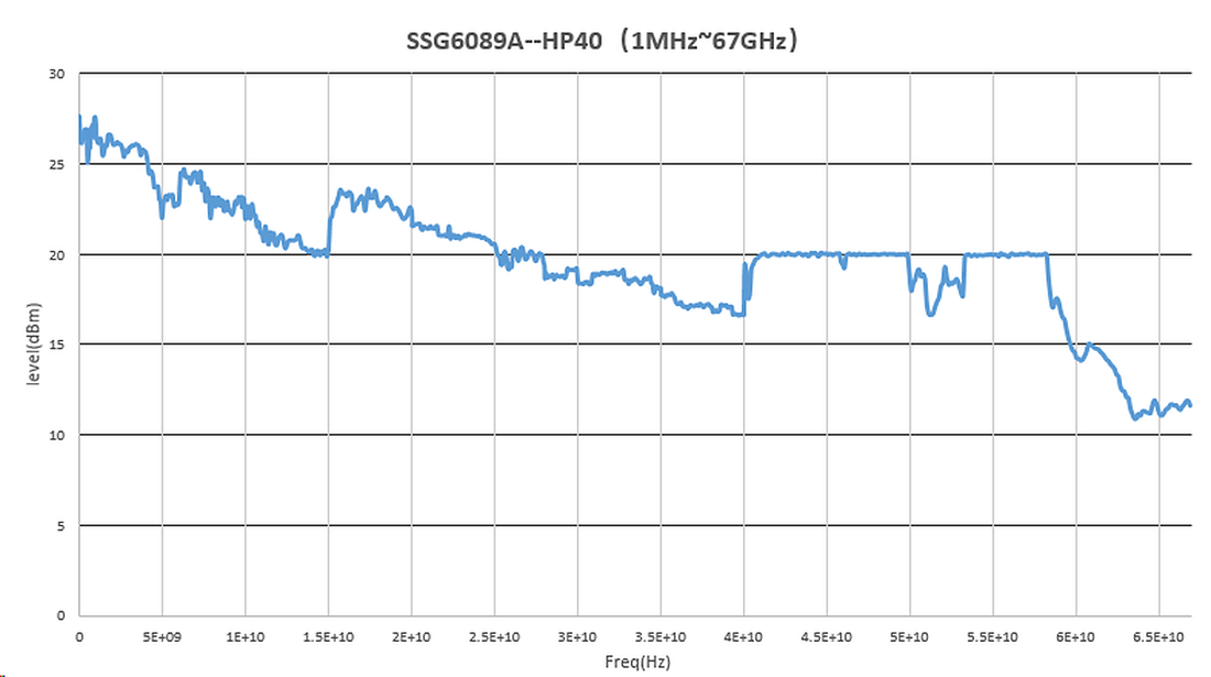
Measured maximum power with option HP40, 1 MHz to 67 GHz (data sheet EN03A, not a guaranteed specification).
Phase noise: standard, or 10 to 13 dB better
Close-in phase noise sets the floor for receiver sensitivity tests, ADC clocking and local-oscillator substitution. The SSG6089A is specified at −135 dBc/Hz at 1 GHz and 10 kHz offset as delivered. The factory option SSG6080A-LPH2 adds a better OCXO and lowers the whole close-in region.
SSB phase noise from the data sheet EN03A, CW mode, 1 Hz bandwidth, level ≤ 10 dBm, 25 ±5 °C. The labelled points are the 10 kHz offset.
| Carrier | 1 kHz std | 1 kHz LPH2 | 10 kHz std | 10 kHz LPH2 | Gain at 10 kHz | 1 MHz std | 1 MHz LPH2 |
|---|---|---|---|---|---|---|---|
| 1 GHz | −126 | −136 | −135 | −148 | 13 dB | −138 | −150 |
| 10 GHz | −105 | −115 | −115 | −128 | 13 dB | −118 | −138 |
| 67 GHz | −88 | −97 | −99 | −109 | 10 dB | −103 | −115 |
dBc/Hz. Data-sheet values; the typical figures in the data sheet are 1 to 5 dB better (−149 dBc/Hz typ. at 1 GHz, 10 kHz with LPH2).
At 1 GHz and 10 GHz the option lowers the noise at 10 kHz offset by 13 dB, a factor of 20 in noise power. At 67 GHz the gain is 10 dB.
Non-harmonic spurs improve from below −50 dBc to below −80 dBc between 4 and 16 GHz, and from −48 dBc to −70 dBc between 40 and 64 GHz. The reference improves to ±30 ppb initial accuracy and 30 ppb ageing per year.
LPH2 and HP40 are fitted in the factory. They cannot be added later with a licence key. Pulse modulation and the pulse train generator can.
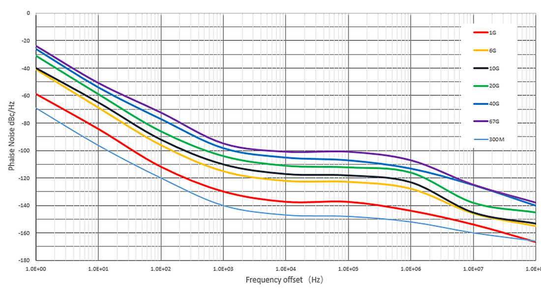
Measured SSB phase noise, standard configuration, carriers from 1 to 67 GHz (data sheet EN03A).
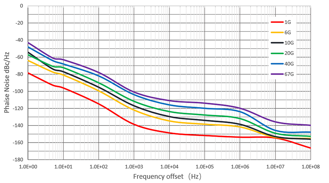
Measured SSB phase noise with option SSG6080A-LPH2 (data sheet EN03A).
The top of the SSG6000A family
The SSG6089A shares the platform, the user interface and the command set of the SSG6000A series. Three things change with the 67 GHz model: the connector, the lowest level and the maximum power.
| Model | Frequency range (CW) | RF connector | Lowest level setting | Specified max. at 1 GHz | High-power option | Availability |
|---|---|---|---|---|---|---|
| SSG6083A | 100 kHz – 13.6 GHz | 2.92 mm | −130 dBm | +22 dBm | HP20 | In the webshop |
| SSG6085A | 100 kHz – 20 GHz | 2.92 mm | −130 dBm | +22 dBm | HP20 | In the webshop |
| SSG6087A | 100 kHz – 40 GHz | 2.92 mm | −130 dBm | +20 dBm | HP40 | In the webshop |
| SSG6089A | 100 kHz – 67 GHz | 1.85 mm | −110 dBm | +18 dBm | HP40 | On request |
Lowest level setting between 3 MHz and 4 GHz. Source: data sheet EN03A.
The 67 GHz output is a 1.85 mm male connector. It mates with 1.85 mm and 2.4 mm connectors, not with 2.92 mm, 3.5 mm or SMA. A 1.85 mm female-to-female adapter is in the box; for a lower-frequency set-up add a 1.85 mm to 2.92 mm adapter.
The 13.6, 20 and 40 GHz models set levels down to −130 dBm. The SSG6089A stops at −110 dBm over its whole range. For receiver sensitivity tests below that, add a fixed attenuator or choose the 40 GHz model.
The RF output is specified for 0 V DC, as printed on the front panel. Use a DC block when the device under test carries a bias voltage. Reverse RF power up to +25 dBm above 6 GHz is tolerated.
Modulation, pulses and sweeps up to 67 GHz
The SSG6089A is an analog source: AM, FM and phase modulation with an internal LF generator are standard, pulse modulation and the pulse train generator are licence options. There is no I/Q modulator.
Internal, external or both sources together.
- AM depth 0 to 100 % in 0.1 % steps
- FM deviation up to N × 5 MHz (typ.): 40 MHz between 40 and 67 GHz
- ΦM deviation up to N × 5 rad
- LF generator: sine 0.01 Hz to 1 MHz, square, triangle, sawtooth, DC; LF output on the front panel
Single and double pulses, internal or external source.
- On/off ratio > 80 dBc (typ.) from 40 to 67 GHz
- Rise and fall time below 15 ns (typ.)
- Pulse width from 20 ns, period from 40 ns, up to 300 s in 10 ns steps
- Pulse overshoot below 8 %, video feed-through below 20 mV
Staggered pulse groups for radar and EW scenarios. Requires the PU option.
- Up to 2,047 different pulses in one train
- On and off time from 20 ns to 300 s for each pulse
- Each pulse repeated 1 to 65,535 times
- Frequency and level sweeps: 2 to 65,535 steps, or a 500-point list, dwell 10 ms to 100 s
What 67 GHz covers
One coaxial output from 100 kHz to 67 GHz, without a banded multiplier or a waveguide extender in the signal path.
Bands inside the range of the SSG6089A. Automotive radar at 76 to 81 GHz lies above it.
5G FR2 components
A CW stimulus, LO or blocker for filters, amplifiers, mixers and antennas in the bands from 24.25 to 48.2 GHz, and in the 57 to 71 GHz band up to 67 GHz.
Satellite and backhaul links
Ka-, Q- and U-band converters and amplifiers, and V-band hardware up to 67 GHz, tested from one source without a frequency extender.
60 GHz communication
The 802.11ad/ay channels 1 to 4 between 57.24 and 65.88 GHz lie inside the range: LO substitution and receiver tests on WiGig front ends.
24 and 60 GHz radar sensors
Stimulus and interference source for short-range radar. Pulse modulation and pulse trains reproduce the timing of the sensor.
Mixers, multipliers and LO chains
+10 dBm specified at 67 GHz is enough for many mixer LO ports without an amplifier. As the input of a multiplier chain, the low phase noise carries through to the higher bands.
Research and metrology
0.001 Hz resolution, an OCXO reference at ±1 ppb over temperature and optional −149 dBc/Hz (typ.) phase noise for physics experiments and reference work.
Options and accessories
Two options are built in at the factory and four can follow later. The request form lists them all.
| Option | Order code | What it adds | How it is supplied |
|---|---|---|---|
| Low phase noise | SSG6080A-LPH2 | Better OCXO; −149 dBc/Hz (typ.) at 1 GHz, 10 kHz; lower spurs; ±30 ppb reference. | Factory-fitted: order with the instrument |
| High output power | SSG6080A-HP40 | 5 to 9 dB more specified power up to 40 GHz; level setting to +30 dBm. | Factory-fitted: order with the instrument |
| Pulse modulation | SSG6080A-PU | Pulse modulator and single / double pulse generator. | Licence key, also later · In the webshop |
| Pulse train generator | SSG6080A-PT | Pulse sequences of up to 2,047 pulses. Requires SSG6080A-PU. | Licence key, also later · In the webshop |
| Rack mount kit | SSG6000A-RMK | 19-inch rack mounting, 2U. | Hardware · In the webshop |
| GPIB interface | USB-GPIB | Adapter from the USB port to GPIB. | Hardware · In the webshop |
In the box
Every SSG6089A is supplied with these items.
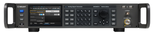
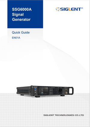
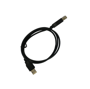
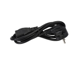

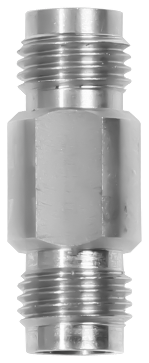
RF cables are not included. At 67 GHz use 1.85 mm cables as short as the set-up allows, tighten the connectors with a torque wrench and inspect them before every connection: a damaged 1.85 mm interface is the most common cause of level errors at these frequencies.
Specifications
The figures that decide a purchase, for the SSG6089A only. The complete tables for the family are in the data sheet below.
| Range (CW) | 100 kHz to 67 GHz |
| Resolution | 0.001 Hz |
| Setting time | < 10 ms (typ.) with ALC on · < 20 ms (typ.) with ALC off (S&H) |
| Reference | OCXO, 10 MHz · ±100 ppb initial · ±1 ppb from 0 to 50 °C · ageing 50 ppb per year |
| Reference with LPH2 | ±30 ppb initial · ageing 30 ppb per year |
| Sweep | Step (linear or logarithmic, 2 to 65,535 points) or list (1 to 500 points) · dwell 10 ms to 100 s |
| Setting range, standard | −110 dBm to +24 dBm (3 MHz to 4 GHz) · to +20 dBm (4 to 67 GHz) |
| Setting range with HP40 | −110 dBm to +30 dBm (1 MHz to 4 GHz) · +26 dBm (4 to 20 GHz) · +23 dBm (20 to 36 GHz) · +20 dBm (36 to 67 GHz) |
| Resolution | 0.01 dB · step attenuator 0 to 110 dB in 10 dB steps |
| Specified maximum output | +18 dBm (3 MHz to 3.4 GHz) · +9 dBm or more to 40 GHz · +18 dBm (40 to 45 GHz) · +15 dBm (45 to 50 GHz) · +10 dBm (50 to 67 GHz) |
| Level error, ALC on, 20 to 30 °C | ≤ 1 dB (maximum to +10 dBm) · ≤ 0.7 dB (+10 to −20 dBm) · ≤ 1 dB (−20 to −90 dBm) · ≤ 2 dB (−90 to −110 dBm, 40 to 67 GHz) |
| VSWR | ≤ 1.6 (nom.) to 6 GHz · ≤ 2 (nom.) from 6 to 67 GHz, level ≤ 0 dBm |
| Reverse protection | 0 V DC · +30 dBm (1 MHz to 6 GHz) · +25 dBm (6 to 67 GHz) |
| SSB phase noise, 10 kHz offset | −135 dBc/Hz at 1 GHz · −115 dBc/Hz at 10 GHz · −99 dBc/Hz at 67 GHz |
| With LPH2 | −148 dBc/Hz at 1 GHz (−149 typ.) · −128 dBc/Hz at 10 GHz · −109 dBc/Hz at 67 GHz |
| Harmonics | < −70 dBc (520 MHz to 10 GHz) · < −65 dBc (10 to 13.1 GHz) · < −75 dBc (13.1 to 18.5 GHz) · < −50 dBc (18.5 to 25 GHz), level ≤ 10 dBm |
| Sub-harmonics | < −80 dBc (1 MHz to 40 GHz, level ≤ 10 dBm). The data sheet prints a second line of −60 dBc with the same frequency range; we confirm the range it applies to in the offer |
| Non-harmonics, offset > 10 kHz | < −60 dBc (to 4 GHz) · < −50 dBc (4 to 40 GHz) · < −48 dBc (40 to 67 GHz) |
| Non-harmonics with LPH2 | < −80 dBc (0.25 to 16 GHz) · < −75 dBc (16 to 32 GHz) · < −70 dBc (32 to 64 GHz) · < −67 dBc (64 to 67 GHz) |
| Wideband noise, 50 MHz offset | < −126 dBc/Hz (40 to 50 GHz) · < −120 dBc/Hz (50 to 67 GHz); with LPH2 < −135 and < −127 dBc/Hz |
| Analog modulation | AM, FM, ΦM · internal, external or both |
| AM | Depth 0 to 100 %, resolution 0.1 % · distortion < 3 % (typ.) at 1 kHz, m < 30 % |
| FM / ΦM deviation | N × 5 MHz (typ.) / N × 5 rad; N = 4 from 25.6 to 40 GHz, N = 8 from 40 to 67 GHz |
| LF generator | Sine 0.01 Hz to 1 MHz · square, triangle, sawtooth to 20 kHz · 1 mVpp to 3 Vpp into 50 Ω |
| Pulse modulation (SSG6080A-PU) | On/off > 80 dBc (typ.) to 13.6 GHz and from 40 to 67 GHz, > 75 dBc (typ.) from 13.6 to 40 GHz · rise/fall < 15 ns (typ.) |
| Pulse train (SSG6080A-PT) | 1 to 2,047 pulses · on/off time 20 ns to 300 s · 1 to 65,535 repetitions |
| RF output | 1.85 mm male, 50 Ω, front panel |
| LF output | BNC, 50 Ω, front panel |
| Rear panel (BNC) | Trigger in/out · external modulation input · pulse in/out · 10 MHz in and out · signal valid |
| Interfaces | LAN (VXI-11, socket, Telnet) · USB device (USBTMC) · USB host · GPIB with the USB-GPIB adapter |
| Supported USB power sensors | R&S NRP6A, NRP18A, NRP8S, NRP18S, NRP33S, NRP40S, NRP50S, NRP67S, NRP40T · Keysight U2000A/B/H, U2001A/B/H, U2002A/H, U2004A (user manual EN01B) |
| Display | 5-inch capacitive touch screen, 800 × 480; mouse and keyboard supported |
| Storage | 4 GB internal flash, USB stick |
| Power | 100 to 240 V, 50/60 Hz · 90 W in data sheet EN03A, 144 W with all options in revision CN03B: allow for 144 W |
| Dimensions (W × H × D) | 482 × 104 × 540 mm |
| Weight | 11.9 kg |
| Environment | Operating 0 to 50 °C, up to 3 km altitude · storage −20 to 70 °C |
Valid within the calibration period, after two hours at room temperature and 40 minutes of warm-up. typ. = typical, nom. = nominal, as defined in the data sheet.
Documentation, firmware and software
Everything Siglent has published for the SSG6000A family, checked on 11 November 2026.
Remote control and automation
- SCPI over LAN (VXI-11, raw socket, Telnet) and USB (USBTMC); works with NI-VISA and any VISA library.
- IVI driver for LabVIEW, LabWindows/CVI and .NET test systems.
- Web browser control from a PC or a mobile device, no software to install.
- Power-meter control: a supported USB sensor on the USB host port for levelling and loss correction.
- GPIB with the USB-GPIB adapter.
Good to know about these documents
- The data sheet EN03A (October 2026) is the first revision with the SSG6089A, the low-phase-noise option and the high-power options.
- The user manual, programming guide and quick start (EN01B, 2024) were written before the 67 GHz model. Operation and commands are the same across the family; the 67 GHz limits are in the data sheet only.
- The English data sheet states a power consumption of 90 W, the later Chinese revision CN03B states 144 W with all options working. Plan the rack supply for 144 W.


Request the SSG6089A
Tick what you need and tell us what you want to measure. We work out the configuration with the Siglent factory and send you an offer by e-mail. Sending the form does not commit you to anything.

- We read it
A person checks the options against your application: LPH2 and HP40 cannot be added later. - Checked with the factory
We confirm the configuration and its options with the Siglent factory. - Your offer by e-mail
Price, delivery time and warranty for your configuration. - Support stays local
Questions before and after delivery: siglent.eu answers them.
Frequently asked questions
The 67 GHz model is offered on request rather than at a fixed webshop price, because the right configuration depends on the application. Send the form on this page: we work out the configuration with the Siglent factory and send you an offer by e-mail. The SSG6083A, SSG6085A and SSG6087A are available directly in the webshop.
No. SSG6080A-LPH2 and SSG6080A-HP40 are fitted in the factory and have to be ordered with the instrument. Pulse modulation and the pulse train generator are licence keys and can be added at any time.
The specified maximum is +10 dBm from 50 to 67 GHz, +15 dBm from 45 to 50 GHz and +18 dBm from 40 to 45 GHz. The high-power option HP40 raises the power up to 40 GHz only.
A 1.85 mm male connector. It mates with 1.85 mm and 2.4 mm connectors, not with 2.92 mm, 3.5 mm or SMA. A 1.85 mm female-to-female adapter is supplied.
No. The SSG6089A is an analog source with AM, FM, phase and pulse modulation. It serves as a CW stimulus, local oscillator or interferer. For I/Q modulation up to 8 GHz see the SSG6082A-V.
No. The range ends at 67 GHz. It covers 24 GHz and 60 GHz radar sensors directly.
Minus 110 dBm over the whole range. The 13.6, 20 and 40 GHz models of the family reach minus 130 dBm.
The standard instrument is specified at -135 dBc/Hz at 1 GHz and -99 dBc/Hz at 67 GHz, both at 10 kHz offset. With LPH2 these become -148 and -109 dBc/Hz. If close-in noise limits your measurement, order the option, because it cannot be retrofitted.
Specifications are taken from the Siglent SSG6000A data sheet EN03A and its revision CN03B, and the SSG6080A user manual EN01B. Specifications are subject to change without notice; errors and omissions excepted. Where a document contradicts itself or another revision we say so on this page and confirm the figure in the offer. siglent.eu is an official Siglent distributor for Europe.