

SSG6M80A Series
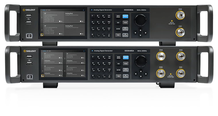
Two or four microwave outputs from 9 kHz to 13.6 or 20 GHz in one 2U instrument, behind one shared reference. Every channel has its own frequency, level and phase setting; in coherent mode the channels hold their relative phase within 1° over five hours up to 5 GHz.
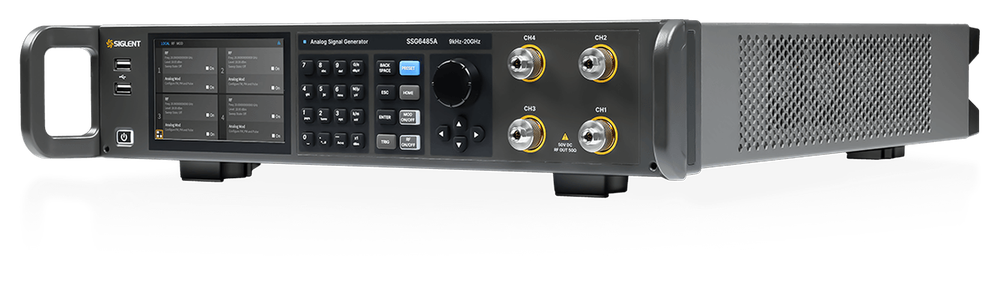
With a multi-channel source, the right number of channels, frequency range and options depend on what you want to measure. So instead of a fixed webshop price we prepare a personal offer: you tell us about your application, and we work out the configuration that fits it with the Siglent factory.
The model you have in mind, the options, the quantity and what you want to measure. The form at the bottom of this page takes two minutes.
We review your application together with the Siglent factory and make sure the instrument and its options fit what you want to do.
By e-mail, with the price, the delivery time and the warranty terms for your configuration. There is no obligation until you accept it.
Phase that stays where you set it
Locking two signal generators to the same 10 MHz reference fixes their frequency, not their phase. Each instrument multiplies the reference up to the carrier in its own synthesizer, and the two results drift against each other with temperature and time. At 10 GHz one period lasts 100 ps, so a drift of 0.42 ps between the two paths already moves the relative phase by 1.5°.
The SSG6M80A puts two or four synthesizer channels behind one OCXO reference and one 1 GHz reference clock. Siglent specifies the result: with coherence switched on, the phase between channels moves by less than 1° up to 5 GHz, less than 1.5° up to 10 GHz and less than 2.5° up to 20 GHz, over five hours and a ±2 °C change in room temperature.
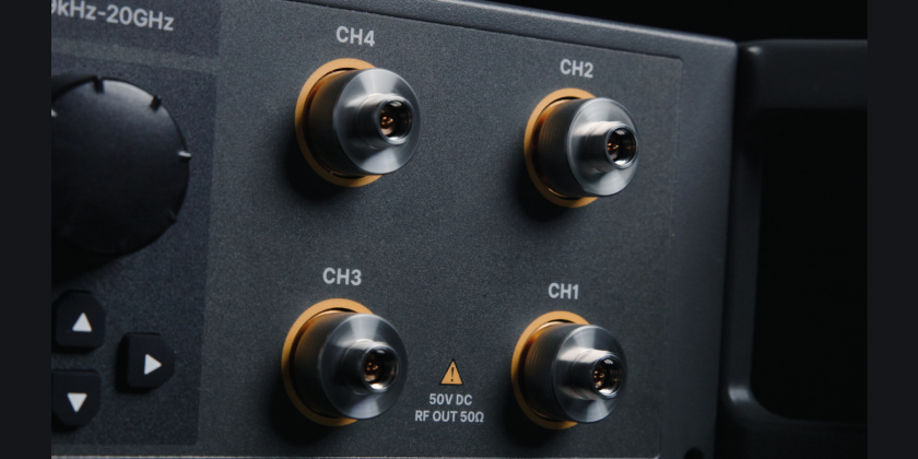
Each output is a complete microwave source in its own right: −135 dBc/Hz phase noise at 1 GHz, a level range from −110 to +25 dBm, 0.001 Hz frequency resolution, FM and phase modulation, and optional pulse modulation. Frequency, level and phase are set per channel on the 5-inch touch screen or over LAN and USB. The four models differ only in the number of channels and the top frequency.
Key highlights
Coherence with a specification
Channel-to-channel drift below 1°, 1.5° and 2.5° per band over five hours, written into the data sheet.
Independent channels
Frequency, level and phase per channel. Phase offset in 0.1° steps over a full 360°.
Phase memory
A channel returns to its locked phase after a frequency change, so a hop does not cost you the calibration.
Scales past four channels
Link units through 10 MHz and 1 GHz on the rear panel to build larger coherent systems.
Four models: two decisions
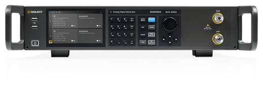
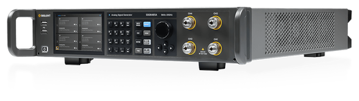
Pick the number of channels and the top frequency. The 13.6 GHz models can be raised to 20 GHz later with an upgrade option. The ordering list contains no upgrade from two to four channels, so the channel count is the decision to get right at the start.
| Model | Channels | Frequency range (CW) | RF outputs | Power consumption | Weight | Frequency upgrade |
|---|---|---|---|---|---|---|
| SSG6283A | 2 | 9 kHz – 13.6 GHz | 2.92 mm male × 2 | 128 W | 10.67 kg | SSG6283A-F85 |
| SSG6285A | 2 | 9 kHz – 20 GHz | 2.92 mm male × 2 | 128 W | 10.67 kg | — |
| SSG6483A | 4 | 9 kHz – 13.6 GHz | 2.92 mm male × 4 | 196 W | 12.97 kg | SSG6483A-F85 |
| SSG6485A | 4 | 9 kHz – 20 GHz | 2.92 mm male × 4 | 196 W | 12.97 kg | — |
All four models share one housing: 482 × 104 × 540 mm (W × H × D), 2U with the SSG6000A-RMK rack kit. Source: data sheet EN01A; dimensions from revision CN01B.
Phase coherence, with the numbers behind it
One reference and one 1 GHz reference clock serve every channel, so the channels cannot drift apart the way separate instruments do. What you get is a specification, not an adjective: the table gives the guaranteed limit per band and what it means in time and in beam direction.
Signal path as described in the data sheet and the user manual. Every channel has its own frequency, level and phase setting; the dashed channels exist on the four-channel models.
Relative phase stability between channels
| Carrier | Drift in 5 h | As a delay | Beam error* |
|---|---|---|---|
| 9 kHz to 5 GHz | < 1° | 0.56 ps | 0.32° |
| 5 GHz to 10 GHz | < 1.5° | 0.42 ps | 0.48° |
| 10 GHz to 20 GHz | < 2.5° | 0.35 ps | 0.80° |
Specification: phase-coherent mode, 5 hours of observation, ambient change ±2 °C (data sheet EN01A). Delay = drift / 360 × one carrier period, at the top frequency of the band (5, 10 and 20 GHz). *Pointing error of a two-element array at half-wavelength spacing, broadside: drift / π.
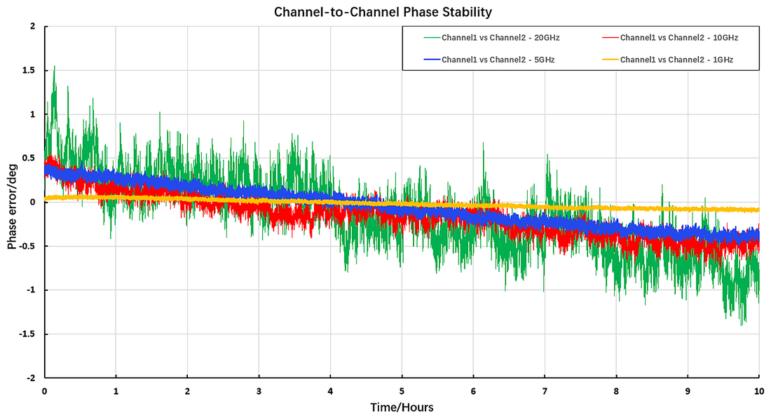
Siglent’s own measurement from the data sheet: phase drift between channel 1 and channel 2 over 10 hours at 1, 5, 10 and 20 GHz, 25 °C ±2 °C. The guaranteed figures are the 5-hour limits in the table.
Three things to know before you plan a test
In phase-coherent mode you select at least two channels and give them one common frequency; level and phase offset stay individual per channel. With coherence off, every channel is an independent generator with its own frequency, for example for a two-tone test.
Phase memory returns a channel to the phase it had locked before a frequency change. A channel runs either in coherent mode or with phase memory, not both at once.
Below 1° holds up to 5 GHz. From 10 to 20 GHz the limit is 2.5°. Plan a phased-array or MIMO test with the figure for your band, not with the best one.
More than four channels: link two units
Two instruments become one phase-referenced system with two cables on the rear panel. The user manual gives the sequence:
- 1Connect 10 MHz OUT of unit A to REF IN of unit B.
- 2Connect 1 GHz OUTPUT of unit A to 1 GHz INPUT of unit B.
- 3Unit A: 1 GHz reference clock internal, 1 GHz output on.
- 4Unit B: 1 GHz reference clock external, then start the synchronisation. The instrument confirms it, or shows UNLOCK when the 1 GHz signal is missing.
The data sheet states that phase coherence is supported across multiple devices; the stability table above is specified for the channels of one instrument.
Two coherent channels, 90° apart, in eight commands
The same sequence as on the touch screen, sent over LAN or USB: select the coherent channels, give them one frequency, synchronise, set level and phase, switch coherence on.
:SOURce1:PHASe:COHerent:CHANnel 1
:SOURce2:PHASe:COHerent:CHANnel 1
:SOURce:PHASe:COHerent:FREQuency 10E9
:SOURce:PHAse:COHerent:SYNC:FREQuency
:SOURce1:POWer:POWer -10
:SOURce2:POWer:POWer -10
:SOURce2:PHASe 90
:SOURce:PHASe:COHerent 1
Commands from the SSG6M80A programming guide EN01A, sections 3.4.3 and 3.4.9. Verify the sequence on your instrument before you build a test system on it.
Signal quality on every channel
Each output is a full microwave source: low phase noise, a wide level range and enough power to drive a mixer or an amplifier input without a booster. The figures apply per channel.
Maximum output power with guaranteed accuracy, per channel (data sheet EN01A). Below 1 MHz the limit is +15 dBm. The level can be set higher, up to +25 dBm between 1 MHz and 15 GHz, without a guarantee on accuracy.
SSB phase noise at 10 kHz offset
| Carrier | Phase noise, 1 Hz bandwidth |
|---|---|
| 100 MHz | < −133 dBc/Hz (nom.) |
| 1 GHz | < −136 dBc/Hz (nom.) |
| 2 GHz | < −128 dBc/Hz (nom.) |
| 4 GHz | < −123 dBc/Hz (nom.) |
| 6 GHz | < −119 dBc/Hz (nom.) |
| 10 GHz | < −115 dBc/Hz (typ.) |
| 20 GHz | < −109 dBc/Hz (typ.) |
CW mode. The headline figure of the series is −135 dBc/Hz at 1 GHz, 10 kHz offset (typ.).
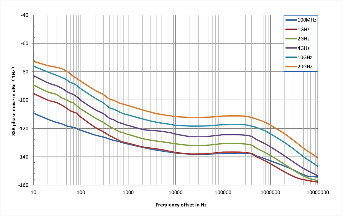
Measured SSB phase noise versus offset for carriers from 100 MHz to 20 GHz (figure 1 of the data sheet).
Level, purity and protection
- Level setting from −110 dBm to +25 dBm (1 MHz to 6 GHz) and −100 dBm to +25 dBm (6 to 15 GHz), in 0.01 dB steps.
- Level error ≤ 0.7 dB between +10 and −20 dBm over the whole range from 100 kHz to 20 GHz, with ALC on at 20 to 30 °C.
- Harmonics below −64 dBc from 2 to 6 GHz and below −68 dBc from 6 to 11 GHz. Between 1 MHz and 2 GHz the limit is −30 dBc: add a low-pass filter where harmonics matter in that range.
- Sub-harmonics below −80 dBc up to 12 GHz, non-harmonic spurs below −60 dBc at more than 10 kHz offset.
- Frequency and level settle in under 10 ms (typ., ALC on).
- Each output tolerates 50 V DC and +30 dBm reverse power up to 6 GHz, +25 dBm above.
- A USB power sensor on the front panel closes the loop: measured power, automatic cable-loss correction and a flatness table.
Modulation and pulses
The SSG6M80A is an analog source. FM and phase modulation are standard on every channel; pulse modulation and the pulse train generator are options. There is no AM and no I/Q modulation in this series.
Internal, external or both sources together.
- FM deviation up to N × 1 MHz: 1 MHz from 6 to 12 GHz, 2 MHz from 12 to 20 GHz
- ΦM deviation up to N × 5 rad
- Modulation frequency response 10 Hz to 100 kHz within 3 dB (nom.)
- FM and ΦM cannot run together; each combines with pulse modulation
Single and double pulses with a pulse output per channel.
- On/off ratio > 80 dBc from 6 to 13.6 GHz, > 75 dBc to 18 GHz, > 70 dBc to 20 GHz, > 60 dBc below 6 GHz
- Rise and fall time below 15 ns (typ.)
- Pulse width from 20 ns, period from 40 ns, both up to 300 s in 10 ns steps
- Trigger: auto, key, external, external gate, bus
User-defined pulse sequences for radar-style bursts.
- Up to 2,047 pulses in one train
- On time and off time from 20 ns to 300 s for each pulse
- Each pulse repeated 1 to 65,535 times
- Frequency and level sweeps with up to 65,535 steps, or a 500-point list
Where a multi-channel source earns its place
Every application below needs more than one microwave signal with a known relationship between them.
Phased arrays and beamforming
Feed two or four elements or sub-arrays with a defined phase per channel in 0.1° steps. At 10 GHz the 1.5° drift limit keeps a half-wavelength pair within 0.48° of its pointing direction for five hours.
MIMO and multi-antenna receivers
Several phase-stable carriers at one frequency for receiver calibration, direction-finding and diversity tests, each with its own level.
Two-tone and multi-tone tests
Two or four clean tones from one instrument with individual level control: intermodulation and TOI on amplifiers and mixers. Add a combiner and, for very linear devices, isolators.
Differential and quadrature drive
Two channels at 180° make a differential signal, at 90° a quadrature LO pair for I/Q mixers and image-reject architectures, tunable in phase to null the imbalance.
Radar and pulsed systems
Coherent carriers with pulse modulation above 80 dBc on/off in X-band, and pulse trains of up to 2,047 pulses, with a pulse output per channel.
LO and clock distribution
One box replaces a rack of single-channel sources as local oscillators for multi-channel converters, with a common OCXO reference at ±1 ppb over temperature.
Options and accessories
Everything on the ordering list of the series. Tick what you need in the request form; the offer states how each option is delivered and whether it covers all channels.
| Option | Order code | What it adds | Type |
|---|---|---|---|
| Pulse modulation | SSG6M80A-PU | Pulse modulator and single / double pulse generator. | Option |
| Pulse train generator | SSG6M80A-PT | Pulse sequences of up to 2,047 pulses. On the single-channel SSG6000A this option needs the pulse modulation option; we confirm the rule for this series in the offer. | Option |
| Frequency upgrade, 2 channels | SSG6283A-F85 | Raises an SSG6283A from 13.6 GHz to 20 GHz. | Upgrade |
| Frequency upgrade, 4 channels | SSG6483A-F85 | Raises an SSG6483A from 13.6 GHz to 20 GHz. | Upgrade |
| Rack mount kit | SSG6000A-RMK | Mounts the instrument in a 19-inch rack, 2U. In the webshop. | Hardware |
| GPIB interface | USB-GPIB | Adapter from the USB port to GPIB. In the webshop. | Hardware |
In the box
Every SSG6M80A is supplied with these items.
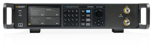
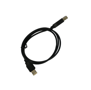
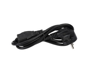

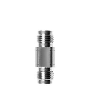
RF cables are not included. Use 2.92 mm (K) cables rated to your top frequency; phase-stable cables of equal length keep the channel-to-channel phase you set at the connector. The data sheet lists the adapter without a quantity; the offer states how many are supplied. A spare 2.92 mm female-to-female adapter is available in the webshop.
Rear panel
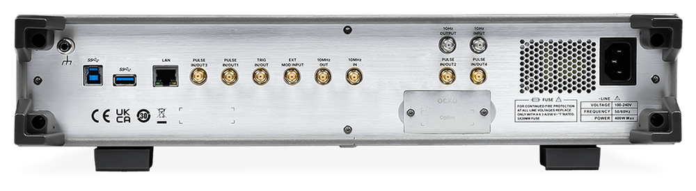
A pulse input/output per channel, trigger, SYNC in/out, external modulation, a reference input (1 to 100 MHz), a 10 MHz output and the 1 GHz input/output pair that links two units. All rear connectors are SMA.
Specifications
The figures that decide a purchase, grouped. The complete tables are in the data sheet below.
| Range (CW) | 9 kHz to 13.6 GHz (SSG6283A, SSG6483A) · 9 kHz to 20 GHz (SSG6285A, SSG6485A) |
| Resolution | 0.001 Hz |
| Setting time | < 10 ms (typ.) with ALC on · < 20 ms (typ.) with ALC off (S&H) |
| Reference | OCXO, 10 MHz · initial accuracy ±100 ppb · ±1 ppb from 0 to 50 °C · ageing 50 ppb per year |
| External reference input | 1 MHz to 100 MHz, −5 to +10 dBm |
| Sweep | Step (linear or logarithmic, 2 to 65,535 points) or list (1 to 500 points) · dwell 10 ms to 100 s |
| Phase offset per channel | 0 to 360° or −180° to +180°, resolution 0.1° |
| Relative phase stability | < 1° (9 kHz to 5 GHz) · < 1.5° (5 to 10 GHz) · < 2.5° (10 to 20 GHz); between channels, 5 h, ±2 °C |
| Phase-coherent mode | Two or more channels at one common frequency; level and phase individual |
| Phase memory | Per channel; restores the locked phase after a frequency change. Not together with coherent mode on the same channel |
| Multi-unit synchronisation | 10 MHz OUT to REF IN and 1 GHz OUTPUT to 1 GHz INPUT |
| Setting range | −110 to +15 dBm (9 kHz to 1 MHz) · −110 to +25 dBm (1 MHz to 6 GHz) · −100 to +25 dBm (6 to 15 GHz) · −100 to +20 dBm (15 to 20 GHz) |
| Resolution | 0.01 dB |
| Specified maximum output | +15 dBm (< 1 MHz) · +23 dBm (1 to 250 MHz) · +24 dBm (0.25 to 4 GHz) · +23 dBm (4 to 6 GHz) · +22 dBm (6 to 14 GHz) · +18 dBm (14 to 18 GHz) · +15 dBm (18 to 20 GHz) |
| Level error, ALC on, 20 to 30 °C | ≤ 1 dB (maximum to +10 dBm) · ≤ 0.7 dB (+10 to −20 dBm) · ≤ 1 dB (−20 to −90 dBm), from 1 MHz to 20 GHz |
| VSWR | ≤ 1.6 (nom.) to 6 GHz · ≤ 1.8 (nom.) to 20 GHz, level ≤ 0 dBm |
| Reverse protection | 50 V DC · +30 dBm (1 MHz to 6 GHz) · +25 dBm (6 to 20 GHz) |
| Harmonics | < −30 dBc (1 MHz to 2 GHz) · < −64 dBc (2 to 6 GHz) · < −68 dBc (6 to 11 GHz) · < −52 dBc (typ., 11 to 14 GHz) |
| Sub-harmonics | < −80 dBc (1 MHz to 12 GHz) · < −70 dBc (12 to 20 GHz) |
| Non-harmonics | < −60 dBc at offsets above 10 kHz |
| SSB phase noise, 10 kHz offset | < −136 dBc/Hz at 1 GHz (nom.) · < −115 dBc/Hz at 10 GHz (typ.) · < −109 dBc/Hz at 20 GHz (typ.) |
| Analog modulation | FM and ΦM, internal, external or both; no AM |
| FM deviation | N × 1 MHz maximum (N = 1 from 6 to 12 GHz, 2 from 12 to 20 GHz) |
| ΦM deviation | N × 5 rad maximum |
| Pulse modulation (option PU) | On/off > 60 dBc (1 MHz to 6 GHz), > 80 dBc (6 to 13.6 GHz), > 75 dBc (to 18 GHz), > 70 dBc (to 20 GHz) · rise/fall < 15 ns (typ.) |
| Pulse generator | Single or double pulse · width 20 ns to 300 s · period 40 ns to 300 s · resolution 10 ns |
| Pulse train (option PT) | 1 to 2,047 pulses · on/off time 20 ns to 300 s · 1 to 65,535 repetitions per pulse |
| RF outputs | 2 or 4 × 2.92 mm male, 50 Ω, front panel |
| Rear panel (SMA) | Pulse in/out per channel · trigger in/out · SYNC in and out · external modulation input · reference input · 10 MHz output · 1 GHz input and output |
| Interfaces | LAN (VXI-11, socket, Telnet) · USB device (USBTMC) · USB host · GPIB with the USB-GPIB adapter |
| Display | 5-inch capacitive touch screen, 800 × 480 |
| Internal storage | 64 GB flash |
| Power | 100 to 240 V, 50/60 Hz · 128 W (2 channels) · 196 W (4 channels) |
| Dimensions (W × H × D) | 482 × 104 × 540 mm |
| Weight | 10.67 kg (2 channels) · 12.97 kg (4 channels) |
| Environment | Operating 0 to 50 °C · storage −20 to 70 °C |
Valid within the calibration period, after two hours at room temperature and 40 minutes of warm-up. typ. = typical, nom. = nominal, as defined in the data sheet.
Documentation, firmware and software
Everything Siglent has published for the series, checked on 11 November 2026.
Remote control and automation
- SCPI over LAN (VXI-11, raw socket, Telnet) and USB (USBTMC); works with NI-VISA and any VISA library.
- Web control: operate the instrument from a browser on a PC or tablet (VNC in the browser, password protected).
- FTP file transfer with TLS for state files, sweep lists and flatness tables.
- LXI web page and network reset (LCI) on the instrument.
- GPIB with the USB-GPIB adapter; address 1 to 30.
Good to know about these documents
- The English user manual has not been published yet. A Chinese edition (CN01A, 87 pages) exists; the facts on this page that go beyond the data sheet come from it and from the programming guide.
- No firmware file is listed for the SSG6M80A yet. The instrument is delivered with the current release and updates from a USB stick.
- Dimensions: data sheet EN01A prints 338 × 113 × 369 mm, the later revision CN01B 482 × 104 × 540 mm. We use the later figure: it is the housing of the SSG6000A, which takes the same rack kit.
Single-channel and vector alternatives


Request the SSG6M80A
Tick what you need and tell us what you want to measure. We work out the configuration with the Siglent factory and send you an offer by e-mail. Sending the form does not commit you to anything.
- We read it
A specialist checks your configuration against your application. - Checked with the factory
We confirm the configuration and its options with the Siglent factory. - Your offer by e-mail
Price, delivery time and warranty for your configuration. - Support stays local
Questions before and after delivery: siglent.eu answers them.
Frequently asked questions
The series is offered on request rather than at a fixed webshop price, because the right configuration depends on the application. Send the form on this page: we work out the configuration with the Siglent factory and send you an offer by e-mail.
All channels run from one OCXO reference and one 1 GHz reference clock. In phase-coherent mode the selected channels run at one common frequency and keep their relative phase: the drift is specified below 1 degree up to 5 GHz, 1.5 degrees up to 10 GHz and 2.5 degrees up to 20 GHz, over 5 hours with a 2 degree Celsius change in ambient temperature.
Yes. Frequency, level and phase are set per channel. Phase-coherent mode is the exception: the coherent channels share one frequency, while level and phase offset stay individual.
Two or four in one instrument. For more, two units are linked with the 10 MHz and 1 GHz reference connections on the rear panel.
The 13.6 GHz models can be upgraded to 20 GHz (SSG6283A-F85 and SSG6483A-F85). The ordering list contains no upgrade from two to four channels.
No. The series offers FM and phase modulation as standard and pulse modulation and a pulse train generator as options. For AM choose the single-channel SSG6000A, for I/Q the SSG6082A-V.
The RF outputs are 2.92 mm male connectors; a 2.92 mm female-to-female adapter is included. All rear-panel signals use SMA.
Phase memory returns a channel to the phase it had locked before a frequency change, so a frequency hop does not lose the phase relationship. On a given channel it cannot be combined with phase-coherent mode.
Specifications are taken from the Siglent SSG6M80A data sheet EN01A and its revision CN01B, the programming guide EN01A and the user manual CN01A. Specifications are subject to change without notice; errors and omissions excepted. Where a document contradicts itself or another revision we say so on this page and confirm the figure in the offer. siglent.eu is an official Siglent distributor for Europe.