

TekBox TBTC1 Open TEM Cell, 50 mm Septum, for EMC Pre-Compliance Testing (with Termination and DC Block)
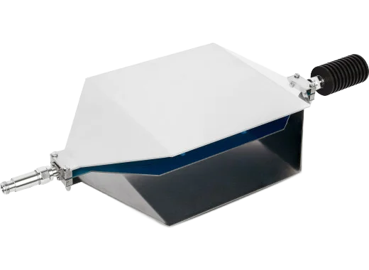
TekBox TBTC1 open TEM cell, 50 mm septum: radiated emission and immunity tests on your bench with a Siglent analyser. Termination and DC block included.
TBTC1 — an open TEM cell that puts radiated-emission testing on the bench, next to the spectrum analyser
A 390 × 200 × 108 mm 50 Ω stripline cell with a 50 mm septum: a board of up to 19 × 13 × 5 cm goes under the septum, one N port is terminated and the other feeds the spectrum analyser. Return loss better than 20 dB to 1.2 GHz and 14 dB to 3 GHz; transmission loss under 1 dB to 1.4 GHz. Termination, DC block and N cable are in the box.
The septum works as a broadband antenna. Whatever the device under test radiates couples into the stripline and arrives at the analyser; whatever a generator feeds into the stripline becomes a field across the DUT. The cell is open at the sides, so the board, its cables and its power lead are placed without taking anything apart — and TekBox’s damping of the higher-order modes keeps the response usable well above where a classical TEM cell of this size resonates.
What it gives you is not the number a test house will measure — there is no honest conversion from TEM-cell voltage to field strength at 3 or 10 m. What it gives you is a repeatable measurement on your own bench: a spectrum before a change and after it, on the same cell with the same settings. TekBox’s rule of thumb: with the board 1 to 2 cm above the floor of the cell, anything above about 40 dBµV deserves a look before the product goes for compliance testing.
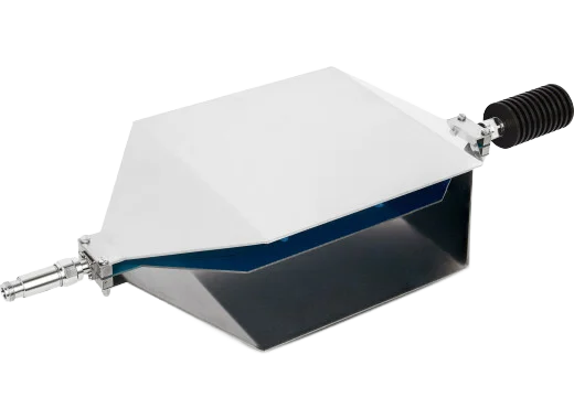
What is in the box
The cell and the three parts that make it a measurement set-up. The DC block protects a DC-coupled analyser input; the termination sets the far end of the stripline.
| Item | Specification |
|---|---|
| TBTC1 open TEM cell | 390 × 200 × 108 mm, septum height 50 mm, N-female ports, 50 Ω nominal, 377 Ω wave impedance |
| RF termination 50 Ω-3 GHz-25 W-N | N-male, DC to 3 GHz, VSWR ≤ 1.2, 25 W continuous, third-order intermodulation ≤ 120 dBc. Sets the 25 W input limit of the cell. |
| DC block 50 V-6 GHz-N | N-male / N-female, 500 kHz to 6 GHz, VSWR ≤ 1.2, 2 W, 50 V RMS. Insertion loss 0.02 dB from 10 to 100 MHz, 0.06 dB at 1 GHz, 0.2 dB at 3 GHz; 1.5 dB at 1 MHz, 3 dB at 700 kHz. |
| Coaxial cable | N-male to N-male |
Four jobs it does on a Siglent bench
Emissions before and after
The main job: a radiated spectrum of the board on the bench, saved, then measured again after a layout, filter or shielding change — same cell, same settings, same scale.
Find the frequency, then the source
The cell tells you which frequencies are too high. The TBPS01 near-field probes then tell you which component or trace produces them.
Immunity sweep
Fed from a tracking generator and an amplitude-modulated amplifier the cell becomes a field generator: tens of V/m across the board from a few watts (table below).
Compare variants
Two PCB revisions, two cable routings, with and without a ferrite: the cell ranks them in minutes, which an anechoic chamber booking never does.
Measuring emissions, and generating a field
The emission procedure from TekBox’s manual, and what the same cell does for immunity testing when the analyser is replaced by a generator and amplifier.
Radiated emissions in five steps
Screw the 50 Ω / 25 W termination on either N port. The DC block goes on the other port and the N cable from there to the analyser input.
Input attenuation 0 dB, preamplifier on if the analyser has one, resolution bandwidth 9 kHz (or what the standard asks for), trace on max hold.
Run a few sweeps with the device under test switched off: that trace is the ambient and the cable pick-up. Then power the DUT and let max hold collect sweeps until pulsed and sporadic emissions are caught.
Scan with the peak detector to find the problem areas. Measure what looks close to a limit again with the quasi-peak detector over a reduced span — the EMI option on the SSA3000X family adds that detector and the CISPR bandwidths.
Save the screenshot, change the design, measure again with the same settings. Any dB the spur loses in the cell it will also lose at the test house.

Immunity: field strength from RF power
With the DUT midway between floor and septum, E ≈ √(P × 50 Ω) × 20 for the 50 mm septum — TekBox’s table for the TBTC1:
| RF power into the cell | Field between septum and floor |
|---|---|
| 10 mW (10 dBm) | 14 V/m |
| 100 mW (20 dBm) | 44 V/m |
| 1 W (30 dBm) | 141 V/m |
| 10 W (40 dBm) | 447 V/m |
The 10 V/m of the industrial immunity standards needs about 5 mW; automotive specifications of several hundred V/m need the full 10 W. Signals are usually amplitude or pulse modulated, so the source is a tracking generator plus a modulated amplifier — ask us for TekBox’s TBMDA range. The field falls about 30 dB per metre outside the cell.
The septum carries the RF; the floor and walls are ground. Put the board on a few millimetres of foam or plastic, never directly on the metal, and use the DC block for a DC-coupled analyser or receiver input. The 25 W input limit is set by the supplied termination.
Specification
| Order code | TBTC1 (TekBox) |
| Type | Open TEM cell (no side walls), 50 Ω stripline |
| Dimensions | Length 390 mm × width 200 mm × height 108 mm |
| Septum height | 50 mm |
| Space under the septum | 19 × 13 × 5 cm |
| Connectors | N-female, both ends |
| Impedance | 50 Ω nominal; wave impedance 377 Ω |
| Maximum RF input power | 25 W (limited by the supplied termination) |
| Input return loss S11 | < −20 dB to 1.2 GHz · < −17 dB to 2.1 GHz · < −14 dB to 3 GHz |
| Transmission loss | < 1 dB to 1.4 GHz · < 3 dB to 2.1 GHz · < 6 dB to 3 GHz |
| Field outside the cell | Falls about 30 dB per metre |
| Supplied | RF termination 50 Ω-3 GHz-25 W-N, DC block 50 V-6 GHz-N, N-male to N-male cable |
From the TekBox TEM cell manual V1.5 (TBTC0/1/2/3), June 2025. The TBTC0 (28 mm septum), TBTC2 (100 mm) and TBTC3 (150 mm) are available on request.
The other TekBox products we stock
Everything from TekBox on siglent.eu, chosen to work with Siglent spectrum analysers. The TekBox category page explains how they fit together.
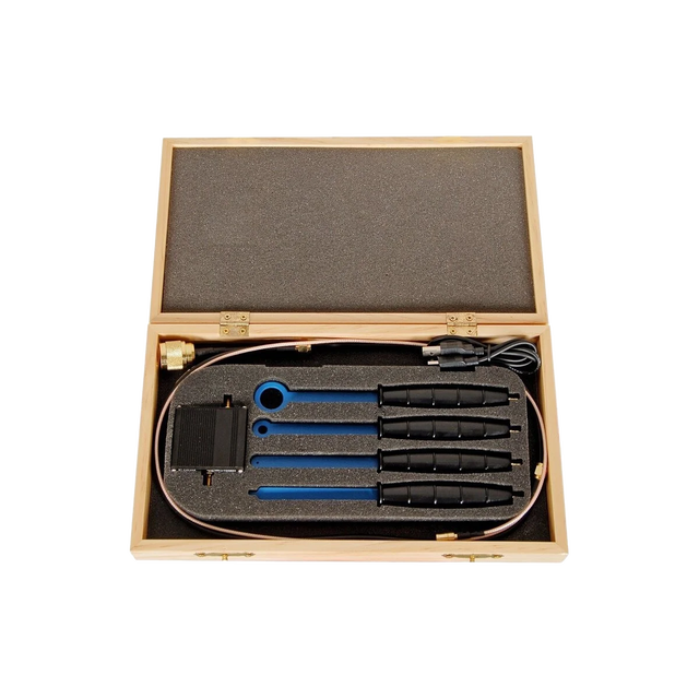
Three H-field loops (20, 10, 5 mm) and an E-field probe, with a 20 dB or 40 dB preamplifier powered from the analyser’s USB port. 2 MHz to 6 GHz.
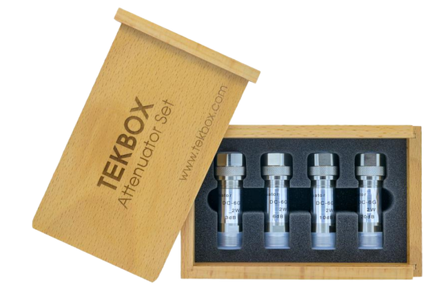
3, 6, 10 and 20 dB N-type attenuators, DC to 6 GHz, 2 W, VSWR below 1.2, in a beech-wood box. Fifteen values from 3 to 39 dB when stacked.
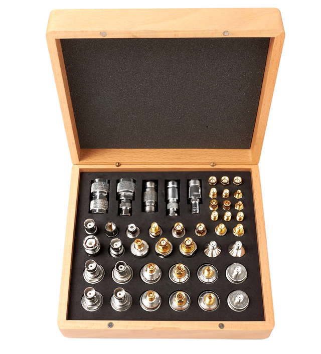
44 adaptors in 25 types between N, SMA, BNC, SMB and RCA, all 50 Ω, N and SMA rated to 6 GHz, in a beech-wood box.
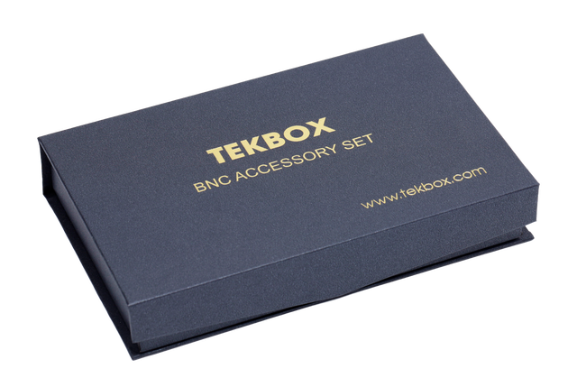
Seven pieces: BNC to 4 mm banana plugs and jacks, BNC to screw terminal block, and a 50 Ω feed-through termination.
Prices ex VAT.
Questions about the TBTC1
Will the TEM cell give me the same result as the test house?
No, and TekBox is clear about it: the voltage at the cell output cannot be converted into the field strength an antenna measures at 3 or 10 m. It gives you a repeatable relative measurement. Measure the failing product in the cell, read from the test report how many dB are missing, and improve the design until the spur has dropped by that amount in the cell.
How big a device fits?
The space under the septum is 19 × 13 × 5 cm. The cell is open at the sides, so cables and a power lead can leave freely; the board itself must stay inside that volume and insulated from septum and floor. For larger products TekBox makes the TBTC2 (100 mm septum) and TBTC3 (150 mm).
Do I need the DC block?
Use it whenever the analyser or receiver input is DC coupled or you are not sure what DC the DUT’s wiring might put on the line. It costs 0.02 dB between 10 MHz and 100 MHz and 0.2 dB at 3 GHz, and only below 1 MHz does its loss become noticeable.
Which Siglent spectrum analyser should I use with it?
Any SSA3000X, SSA3000X Plus, SSA3000X-R or SSA5000A works; set attenuation to 0 dB, switch the preamplifier on and use 9 kHz RBW with max hold. The EMI measurement option for these families adds the quasi-peak detector and the CISPR 6 dB bandwidths that the standards specify — useful once a spur is close to a limit.
Can I do immunity tests with it?
Yes. Terminate one port and drive the other from a swept generator and an amplifier; the field across the DUT follows the table above — 10 V/m from about 5 mW, 141 V/m from 1 W. The standards call for modulated signals, so the usual source is the analyser’s tracking generator feeding a modulated amplifier such as TekBox’s TBMDA series, which we supply on request.
Does the open cell pick up ambient noise?
A little, and the manual’s procedure deals with it: sweep with the DUT switched off first. Signals that are still there are ambient or picked up by the DUT’s cables, not emitted by it. A shielded tent or bag over the set-up removes them if they get in the way.
Is 3 GHz the upper limit?
It is where the specification stops. Most radiated-emission limits run from 30 MHz to 1 GHz, where the TBTC1 loses less than 1 dB; to 2.1 GHz the loss stays under 3 dB and to 3 GHz under 6 dB. For the GHz range on larger products TekBox’s GTEM cell is the next step.
Setting up pre-compliance testing?
Tell us what you build and which standard it has to meet. We put together the cell, the probes, the analyser and — for immunity — the amplifier, and quote the set.