

Siglent DPB5150A 100MHz Differential High-Voltage Probe
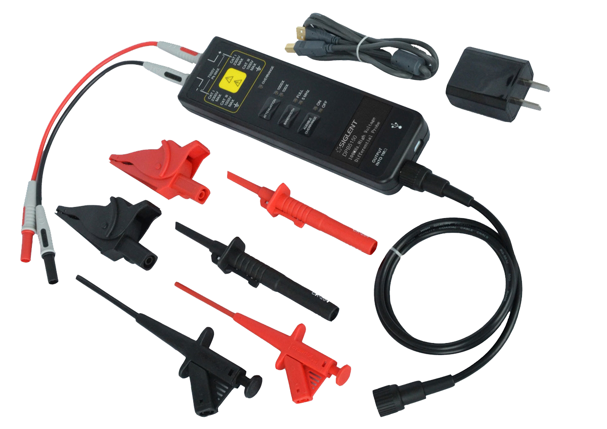
Siglent DPB5150A 100MHz Differential High-Voltage Probe with a maximum input differential voltage: 1500 V (DC + AC)
100 MHz differential high-voltage probe, ±1,500 V
The DPB5150A measures up to ±1,500 V between its two tips with 100 MHz of bandwidth, a ≤3.5 ns rise time and ±2% DC accuracy. The A model is the fast version of the DPB5150: 100 MHz and a 3.5 ns rise time instead of 5 ns.
Neither tip is referenced to earth, which is the entire point: you can put it across a floating rail, a high-side gate-source or a mains-referenced switch node without connecting that point to earth through the instrument. Two attenuation ratios — 50X up to ±150 V for the lowest noise, 500X for the full range. The extra speed is what makes it usable on wide-bandgap switching, where the edge itself is the measurement.
Before you order
Compare the DPB6150A before you order. At €750 it is €330 cheaper and matches this probe exactly on bandwidth (100 MHz), attenuation (50X/500X) and differential range (±1,500 V between the tips). It also tolerates more common-mode voltage — how far the probe pair may float above earth — at 1000 V CAT III / 600 V CAT IV against this probe’s 600 V CAT III / 1000 V CAT II. Those are two different limits and both apply at once: the differential rating is what you may measure, the common-mode rating is where you may measure it. On paper the newer probe wins on both — ask us if you would like help deciding.
What it does well
The things that decide whether a high-voltage measurement is both accurate and safe.
No earth reference at the tips
A passive probe’s ground clip is wired to the oscilloscope chassis and therefore to mains earth. This one measures the difference between two floating points and sends only that difference to the scope, so the circuit never sees an earth connection.
100 MHz bandwidth, ≤3.5 ns rise time
The rise time is the number that matters on a switching edge — it decides whether you see the real overshoot and ringing or a rounded approximation of them.
3.5 ns rise time
Half the rise time of the 70 MHz version for the same voltage rating. On a SiC or GaN half-bridge that is the difference between seeing the real overshoot and seeing it rounded off.
Rated 600 V CAT III · 1000 V CAT II
The measurement category describes the transient energy the installation can deliver, not just the voltage it sits at. Match the category to where you are probing first.
Over-range indicator and alarm
A red indicator and an audible alarm the moment the input exceeds the selected range, so a clipped trace gets noticed on the bench. The alarm can be silenced when it becomes a nuisance.
CMRR better than 80 dB at DC
>80 dB at DC, >60 dB at 100 kHz and >50 dB at 1 MHz. Common-mode rejection is what stops a large floating voltage swamping the small differential signal you actually want.
Key specifications
- Bandwidth 100 MHz (−3 dB), rise time ≤3.5 ns
- Maximum differential input ±1,500 V
- Attenuation 50X and 500X
- ±2% DC accuracy
- Common mode to earth: 600 V CAT III · 1000 V CAT II
- Input impedance 5 MΩ single-ended / 10 MΩ across the inputs
- Input capacitance <4 pF / <2 pF
- Noise <50 mV at 50X, <300 mV at 500X
Application examples
Half-bridge and gate-drive measurement
High-side gate-source voltage on a bridge floats by definition. This is the measurement that destroys probes and oscilloscope front ends when it is attempted with a passive probe and a ground clip.
Motor drives and inverters
Phase-to-phase and DC-link voltage on a drive, where nothing in the measurement sits at earth potential and the common-mode swing is large.
Switch-mode power supply design
Switch-node voltage, snubber behaviour and rectifier stress — the measurements that decide component ratings, efficiency and how long the supply lasts.
Mains and power-line work
Directly across a live conductor, safely, with the measurement category matched to where you are probing rather than just the voltage.
SiC and GaN converter development
Fast wide-bandgap edges with several hundred volts of swing, where bandwidth decides whether the ringing you are chasing is visible at all.
Specifications
| Bandwidth (−3 dB) | 100 MHz |
|---|---|
| Rise time | ≤3.5 ns |
| DC accuracy | ±2% |
| Attenuation ratios | 50X and 500X |
| Maximum differential test voltage (DC + peak AC) | ±150 V at 50X · ±1,500 V at 500X |
| Maximum common-mode voltage to earth | 600 V CAT III · 1000 V CAT II |
| Input impedance | 5 MΩ single-ended to ground · 10 MΩ across the two inputs |
| Input capacitance | <4 pF single-ended · <2 pF across the two inputs |
| CMRR | >80 dB at DC · >60 dB at 100 kHz · >50 dB at 1 MHz |
| Noise (Vrms) | <50 mV at 50X · <300 mV at 500X |
| Propagation delay | Probe ≈9 ns · BNC lead (1 m) ≈5 ns |
| Bandwidth limit | ≥−3 dB at 5 MHz — switchable |
| Differential overvoltage detection | ≥150 V at 50X · ≥1,500 V at 500X |
| Over-range indication | Red indicator and audible alarm (can be silenced), with automatic save |
| Offset setting | Yes — set in test mode |
| Terminating load | ≥100 kΩ |
| Power | USB 5 V / 1 A adapter |
From the SIGLENT Probe Data Sheet. Maximum differential test voltage is what you may measure between the two tips. Maximum common-mode voltage to earth is how far the pair may float above earth. They are different numbers and both apply at the same time. Errors and omissions excepted.
Other differential probes
Tell us where you are probing
The voltage between the two points, how far they float above earth and how fast the signal moves. Those three answers pick the probe — and we will say plainly when a cheaper one covers it.