

Siglent SNA-TB01 RF Demonstration Board

The Siglent SNA-TB01 is a RF demonstration board with 11 test circuits: mixer, amplifier, coupler, balun, filters, TDR and differential lines. USB-C powered, SMA ports.
Eleven RF circuits, ready for the analyser
Learning a vector network analyser properly needs things to measure that behave in known, interesting ways — a mixer that converts, an amplifier that compresses, a coupler with real directivity, a line whose impedance steps up and down. Building those takes time, and borrowing a product from the bench risks breaking it.
The SNA-TB01 puts eleven of them on one board behind SMA connectors: two 50 Ω through lines, a wideband active mixer, a DC–15 GHz amplifier, a 3–5 GHz directional coupler, a balun, a low-pass and a band-pass filter, an impedance transformation line, and a 100 Ω differential line with its own transformation line.
Together they cover the measurements people buy an analyser for: S-parameters, gain and compression, conversion loss, coupling and directivity, mixed-mode and CMRR, filter bandwidth and delay, and impedance against distance with TDR. The 40-page manual gives a step-by-step test for every circuit, with the expected result. The mixer and amplifier are powered from the analyser’s own USB port.
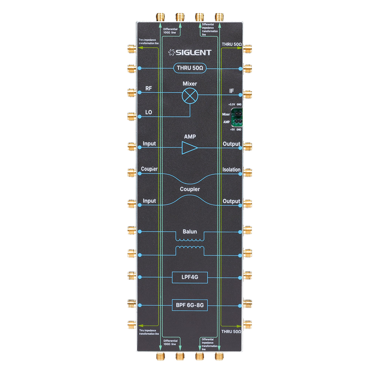
The eleven circuits
What each one is, what you measure on it, and what the analyser needs. All figures are from the SNA-TB01 user manual.
| Circuit | Key figures | What you measure | The analyser needs |
|---|---|---|---|
| 50 Ω short through line | Microstrip, 50 Ω | S11, S21, S12, S22 · transmission loss, return loss, SWR | Any 2-port analyser |
| Mixer · LTC5562 | RF 30 MHz–7 GHz at −12 dBm · IF 2–500 MHz · LO −1 dBm · up- and down-conversion · +3.3 V from USB-C | Conversion loss or gain (S21), input and output match (S11, S22), IF-to-RF isolation (S12) | Scalar mixer measurement (SMM) option · LO from port 3 of a 4-port analyser, or from an external RF source · a USB power meter for power calibration |
| Amplifier · MAAM-011206 | DC–15 GHz · 13.5 dB gain and 18 dBm OP1dB at 6 GHz (typical) · +5 V from USB-C or external DC bias | Gain, return loss, isolation, K-factor, 1 dB compression (IP1dB, OP1dB), harmonic distortion | Any 2-port analyser · power sweep for compression · spectrum analyser option for harmonics |
| Directional coupler | 3–5 GHz · input, output, coupled and isolated ports | Input return loss, insertion loss, coupling (S31), isolation (S41), directivity | 4-port analyser recommended · on a 2-port, terminate the unused ports in 50 Ω and measure one pair at a time |
| Balun · TC1-1-13MG2+ | 4.5 MHz–3 GHz | Differential return loss (Sdd11), differential insertion loss (Sdd21), CMRR (Sdd21/Scc21) | 4-port analyser with balanced measurement · a 2-port can only show Sdd11 |
| Low-pass filter | 4 GHz cut-off | Cut-off frequency, insertion loss, return loss, group delay, out-of-band rejection | Any 2-port analyser |
| Band-pass filter | 3–3.9 GHz passband (user manual) | Bandwidth, centre frequency, Q, insertion loss, passband ripple, delay ripple | Any 2-port analyser · segmented sweep speeds it up |
| 50 Ω long through line | About 21 cm · dielectric constant 3.48 | S-parameters, and impedance against distance | Any 2-port analyser · TDR option for impedance against distance |
| Impedance transformation line | 50 → 75 → 25 → 50 Ω along about 21 cm · dielectric constant 3.48 | Return loss, and the impedance profile along the line | TDR option |
| 100 Ω differential line | About 21 cm · dielectric constant 3.48 | Sdd11, Sdd21, Sdd22, and differential impedance against distance | 4-port analyser · TDR option for the impedance profile · a 2-port shows Sdd11 and Sdd22 only |
| Differential impedance transformation line | 100 → 120 → 75 → 100 Ω · dielectric constant 3.48 | Differential return loss, and the differential impedance profile (Tdd11) | 4-port analyser · TDR option |
Power, and two things to respect
Only the mixer and the amplifier are active. Both run from one USB-C cable to the analyser’s USB port, and a power LED shows when they are on.
USB power, and its limit
The mixer gets 3.3 V from an onboard regulator. The amplifier wants +5 V, and losses in its bias circuit leave it short on USB power — gain and compression point then read below the specification. For figures close to it, supply +5 V at 0.1 A through the analyser’s DC bias input on the port connected to the amplifier output.
No DC block on the amplifier output
It is left out deliberately, so the analyser’s DC bias function can be demonstrated. The consequence is that anything connected to the amplifier output can see DC. Check what is on that port before you power it.
Keep the port power at +10 dBm or less
The amplifier adds about 15 dB. The manual sets the analyser’s port power to +10 dBm or below, against a +27 dBm input damage level on the SNA series, and suggests an external attenuator if you need more margin.
What your analyser needs
A basic 2-port analyser covers most of the board. The rest depends on port count and three software options — worth knowing before you plan a course or a demonstration around it.
Any 2-port analyser
Both through lines, both filters and the amplifier — including power-sweep compression — need nothing beyond two ports, cables and a calibration. That is most of the board. Entry point: the SNA5003X-E or SNA5006X-E.
A 4-port analyser
The coupler, the balun and both differential lines are four-port circuits. A 2-port analyser can still measure parts of them with 50 Ω loads on the unused ports, but CMRR and full mixed-mode results need four. The SNA5004A and SNA5014A are 4-port.
Scalar mixer measurement
The mixer is a frequency-converting device, so it needs the SMM option: SNA5000-SMM or the SNA6000 equivalent. The local oscillator comes from port 3 of a 4-port analyser or from an external RF source.
Time-domain reflectometry
To see impedance change along the long, transformation and differential lines, use the TDR option: SNA5000-TDR or SNA6000-TDR. Without it those lines still give ordinary S-parameters.
Spectrum analysis
Watching the amplifier’s harmonics appear as it is driven into compression uses the spectrum analyser function: SNA5000-SA or SNA6000-SA.
Calibration, cables and loads
Every test in the manual starts with a full 2-port or 4-port calibration. The board’s ports are SMA female, so SMA or 3.5 mm calibration standards and test cables such as the SMA-SMA-18L fit directly. Keep 50 Ω loads to hand for 2-port work on the 4-port circuits.
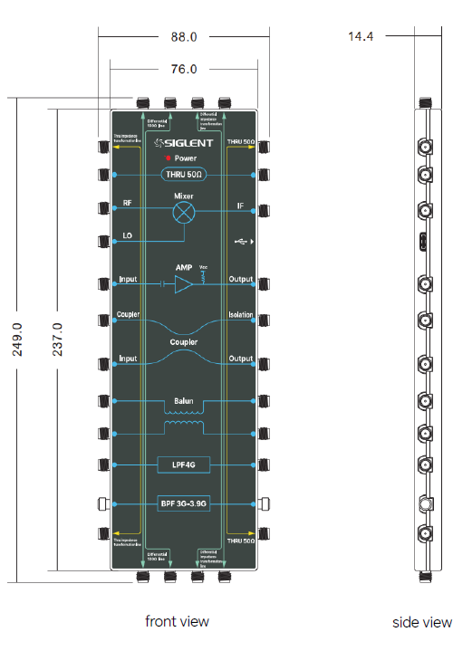
Size and connections
| Overall size | 249 × 88 × 14.4 mm, including connectors |
| Board | 237 × 76 mm for the board itself, without connectors |
| RF connectors | SMA female |
| Power | USB-C, with power indicator |
| Line substrate | Dielectric constant 3.48 — the value to enter for TDR |
User manual
The circuit descriptions, the parameters worth measuring on each, and a step-by-step test for all eleven with the expected screenshots.
Test setups for the SNA series, including SMM, TDR, balanced and spectrum-analysis measurements.
Questions we are asked
Which network analysers does it work with?
Any vector network analyser that can connect to SMA ports. The user manual walks through every test on a Siglent SNA analyser, so the menu steps match those instruments, but the circuits themselves are ordinary 50 Ω and 100 Ω RF structures.
Can I use it with a 2-port analyser?
Yes, for most of the board: both through lines, both filters and the amplifier. The coupler, balun and differential lines are four-port circuits — on a 2-port analyser you terminate the unused ports in 50 Ω and get part of the picture, for example only Sdd11 on the balun. The mixer needs the scalar mixer measurement option.
How is it powered?
From a USB-C cable to the analyser’s own USB port — there is no mains adaptor. Only the mixer and the amplifier need power; the power LED shows when it is on. The mixer runs from an onboard 5 V to 3.3 V regulator.
Why does the amplifier measure below its specified gain?
On USB power, losses in the bias components leave the amplifier below +5 V, so gain and 1 dB compression point come out lower than the MAAM-011206 specification. For figures close to the specification, supply +5 V at 0.1 A through the analyser’s DC bias input on the port connected to the amplifier output.
Can the board damage my analyser?
Two things to respect. The amplifier output has no DC-blocking capacitor — deliberately, so the analyser’s DC bias can be demonstrated — so anything connected to that port can see DC. And the amplifier adds about 15 dB of gain: the manual sets the analyser’s port power to +10 dBm or below, against a +27 dBm input damage level on the SNA series, and suggests an attenuator if you need more margin.
Is the through line a calibration standard?
No. The through lines are devices to measure, not references to calibrate against. Calibrate the analyser and cables first with a proper calibration kit or ECal module, then measure the board.
What does the manual cover?
Forty pages: what each circuit is and which parameters matter, then a step-by-step test for all eleven with the analyser settings, the connections and a screenshot of the expected result.
Goes with
Planning a course or a demonstration?
Tell us which analyser you have and what you want to show. We will confirm which circuits it covers and which options you need — and quote multiples for a training room. JRSE B.V. is the official Siglent distributor for the European Union.