

SDS2000X HD Series
Four-channel 12-bit oscilloscopes at 200 or 350 MHz, upgradable to 500 MHz by software key: 2 GSa/s, 200 Mpts of memory and a 70 µVrms noise floor on a 10.1-inch touchscreen, with sixteen digital channels, a 25 MHz generator and fourteen software options to grow into.
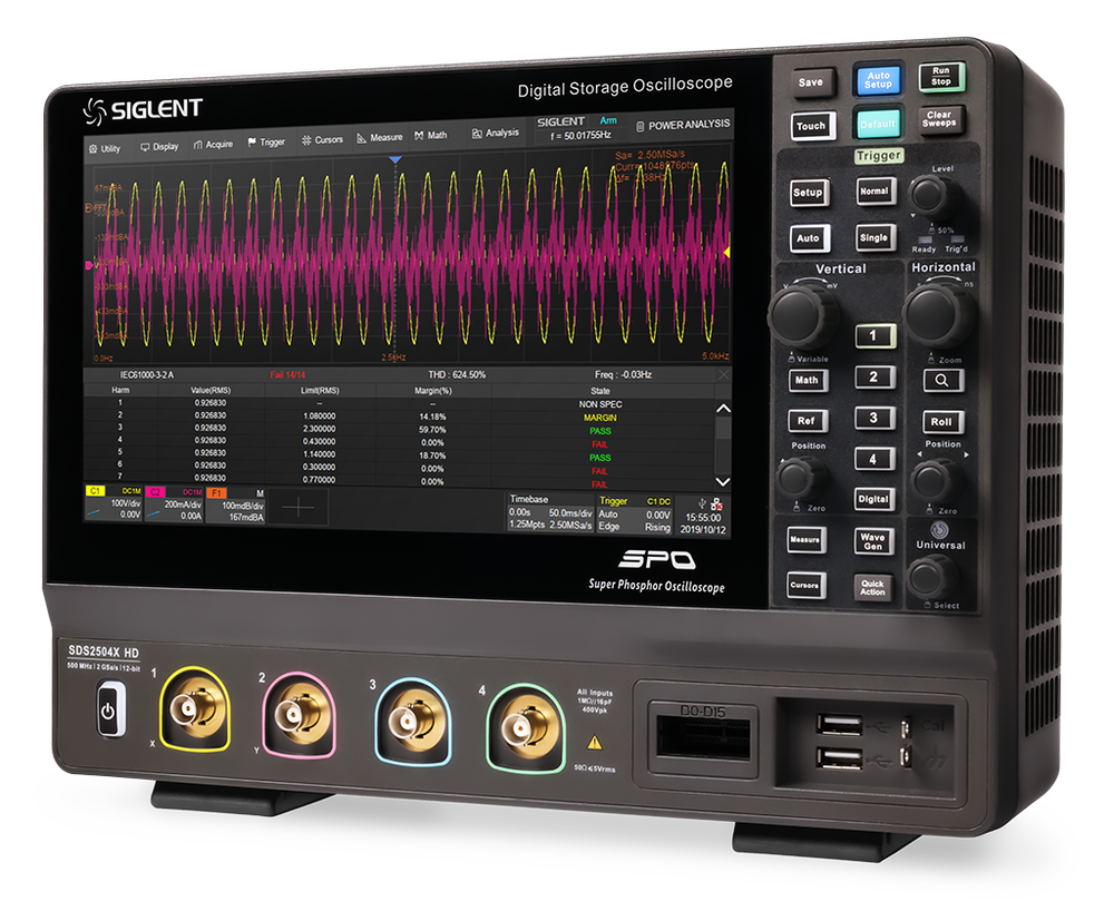
Sixteen times the resolution, where most of the bench work happens
An 8-bit oscilloscope divides the screen into 256 levels. On a 12 V rail that is about 50 mV per step — fine for seeing that the rail is there, useless for seeing 10 mV of ripple on it. The SDS2000X HD divides the same screen into 4,096 levels, and backs the converter with a front end that is quiet enough to use them: 70 µVrms at 500 MHz bandwidth and 0.5 % DC gain accuracy typical.
Around that sit the things a development bench needs every day: 200 Mpts of memory at 2 GSa/s, 100,000 waveforms per second, an 80,000-frame history, sixty-plus measurements with statistics, a 2 Mpts FFT, Bode plot and hardware Mask Test, and trigger and decode for I²C, SPI, UART, CAN and LIN. None of it is an option.
What is optional is listed on this page in full: three bandwidth keys, power analysis, the built-in 25 MHz generator and nine further serial protocols as software keys, the SPL2016 probe for sixteen digital channels, and the probes and accessories Siglent names for the series.
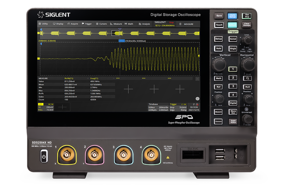
What defines the series
12 bits on a quiet front end
A 12-bit ADC at 2 GSa/s behind a front end with a 70 µVrms noise floor at 500 MHz bandwidth and 0.5 % DC gain accuracy typical. Ripple on a rail or the tail of an edge is measured, not guessed from eight coarse bits.
200 Mpts and 100,000 wfm/s
200 Mpts per channel keeps the full sample rate over long captures. 100,000 waveforms per second (500,000 in Sequence mode) and an 80,000-frame history catch the event that happens once and let you scroll back to it.
Bandwidth is a software key
200 MHz today, 350 or 500 MHz when the project needs it — by key, without sending the instrument anywhere. The supplied probes are already rated 500 MHz.
The analysis is in the box
Bode plot, hardware Mask Test at 14,000 decisions per second, 2 Mpts FFT, 60+ measurements with statistics, search, navigate, DVM and counter are standard, as is decode for I²C, SPI, UART, CAN and LIN.
Two models
Same chassis, same 12-bit acquisition, same memory; they differ in bandwidth. Software keys, probes and accessories are under Options and accessories. Prices exclude VAT.
The entry to the series and the quietest front end of the two: 55 µVrms and 8.6 effective bits. Bandwidth can be raised to 350 or 500 MHz later by software key.
350 MHz on all four channels and 1 ns rise time for faster edges; one key away from 500 MHz. Cheaper than a 200 MHz model plus the upgrade key.
The 100 MHz model has left Siglent’s range. The SDS2204X HD is the entry model now. For owners: the upgrade keys BW1T2, BW1T3, BW1T5 and service remain available.
Side by side
| SDS2204X HD | SDS2354X HD | |
|---|---|---|
| Bandwidth | 200 MHz | 350 MHz |
| Rise time (typ.) | 1.7 ns | 1 ns |
| Noise floor at 1 mV/div (typ.) | 55 µVrms | 65 µVrms |
| ENOB (typ.) | 8.6 bit | 8.4 bit |
| Overshoot on a 150 ps edge (typ.) | 3 % | 12 % |
| Upgrade to 350 MHz | SDS2000HD-BW2T3 · €780 | — |
| Upgrade to 500 MHz | SDS2000HD-BW2T5 · €1,880 | SDS2000HD-BW3T5 · €1,100 |
| Price, excl. VAT | €2,280 | €2,880 |
An SDS2204X HD at €2,280 plus the €780 key to 350 MHz comes to €3,060, against €2,880 for an SDS2354X HD bought outright — €180 more. The same holds on the way to 500 MHz: starting from the 350 MHz model is €180 cheaper. The keys exist for when requirements change, not as a way to spread the cost.
The instrument at work
Four jobs it is bought for, described from what the pictures show.
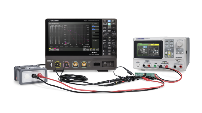
Bode plot of a power supply loop
The oscilloscope sweeps a generator through an injection transformer and measures gain and phase across the feedback divider of the supply on the bench. Gain margin, phase margin and crossover are read from the plot; Vari-level keeps the injected signal small where the loop gain is high. Standard on every model — it needs a source: the FG key, the SAG1021I or an SDG generator.
Power analysis (PA key)
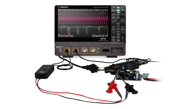
A differential probe on the mains side and a current probe on the line, with the harmonics of the input current checked against IEC 61000-3-2 in a pass/fail table. The same key measures switching loss, inrush, ripple, PSRR, efficiency and SOA.
What twelve bits look like
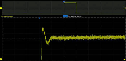
The top of a fast edge, zoomed to 20 mV/div with a 1.46 V offset: the overshoot and the settling tail are drawn as a line rather than as steps. 4,096 levels instead of 256, on a front end quiet enough to use them.
Built-in generator (FG key)
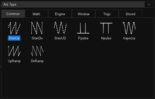
The arbitrary-waveform library of the 25 MHz generator: staircases, pulses, trapezoids and ramps under “Common”, with Math, Engine, Window and Trigonometric families beside them. Waveforms can also be copied straight from a captured channel.
Options and accessories
Everything Siglent lists for the SDS2000X HD: 14 software keys, the logic probe, and the probes and accessories from the data sheet. Software keys are generated for the serial number of your instrument and activated in its menu; the licences page explains how. Prices exclude VAT.
Bandwidth upgrades
Three keys. 500 MHz is reached in interleaving mode — one channel of each pair C1/C2 and C3/C4 active; with both on, the bandwidth is 350 MHz.
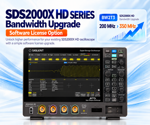
For the SDS2204X HD. Activated by key, no hardware change.
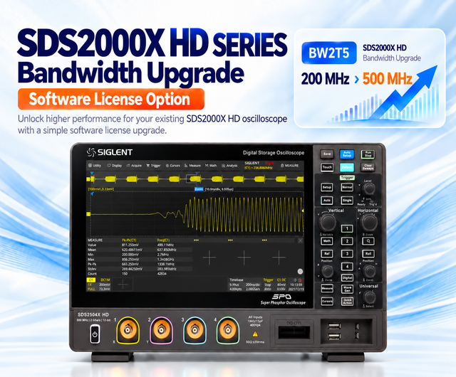
For the SDS2204X HD, in one step. 500 MHz applies in interleaving mode.
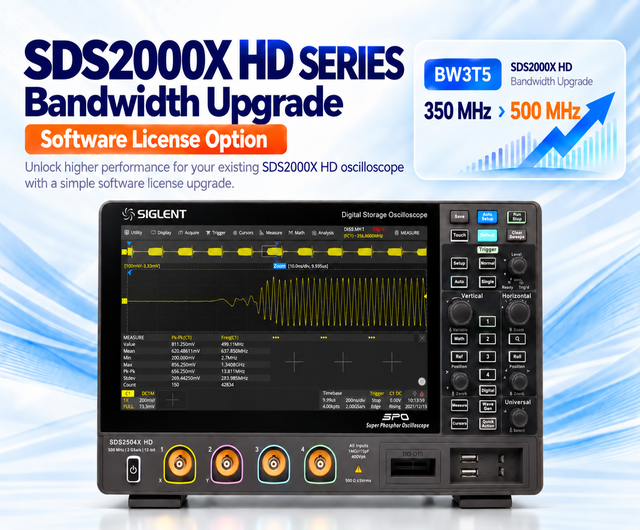
For the SDS2354X HD. 500 MHz applies in interleaving mode.
Analysis and generator
Bode plot, Mask Test, FFT and the measurement suite are standard; these two are not.
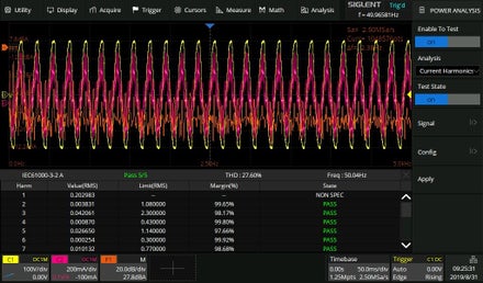
Power quality, current harmonics, inrush current, switching loss, slew rate, modulation, output ripple, turn on/off, transient response, PSRR, efficiency and SOA.
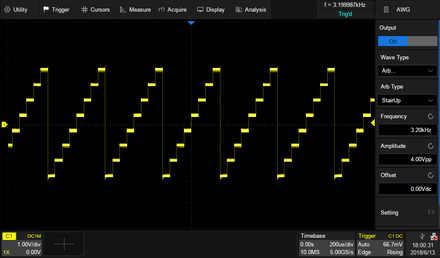
Unlocks the built-in generator: 25 MHz sine, 125 MSa/s, 14-bit, 45 built-in arbitrary waveforms. Also the sweep source for the Bode plot.
Serial buses
I²C, SPI, UART, CAN and LIN are standard. Nine more by key — five with trigger and decode, four with decode only, as marked on each card.
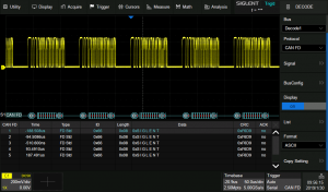
Data rates to 10 Mbps; trigger on start, remote, ID, ID + data and error frames.
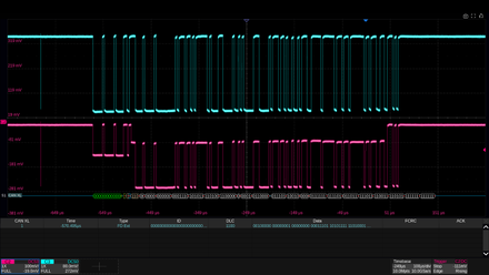
SIC and Fast mode, XL data rates to 20 Mbps, on analogue or digital channels.
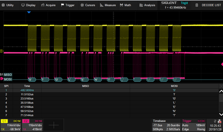
2.5, 5 and 10 Mbps; trigger on TSS, frame, symbol and errors.
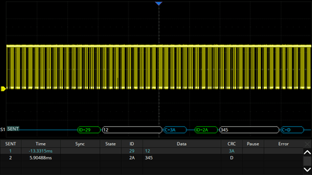
Automotive sensor bus; trigger on start, slow channel, fast channel and errors.
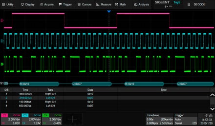
Audio I²S, left- and right-justified; trigger on data, mute, clip and glitch.
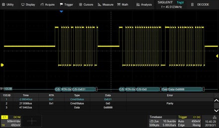
Avionics data bus on the analogue channels; trigger on transfer, word, error and timing.
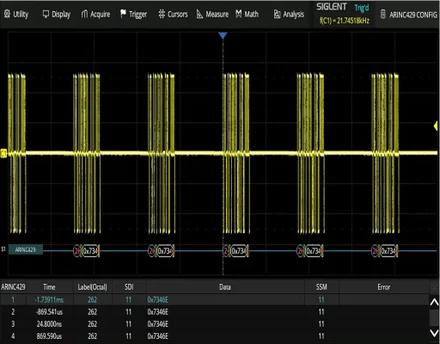
12.5 to 100 kbps with 1–20 % tolerance; label, SDI, data and SSM in the table.
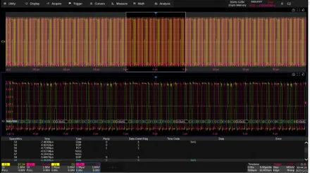
Data and strobe, 2 to 400 Mbps, N/L-character or packet view.
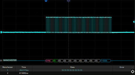
500 bps to 5 Mbps on the analogue channels.
Siglent includes the logic-analyser software in the current firmware of the SDS2000X HD. To turn the oscilloscope into a 4 + 16 channel mixed-signal instrument, add the SPL2016 logic probe and, on an older unit, update the firmware first. Digital channels are sampled at 500 MSa/s into 50 Mpts and can be used as trigger and decode sources.
Hardware
Each oscilloscope ships with a 500 MHz passive probe per channel, USB cable, power cord, quick start, calibration certificate and a wireless mouse.
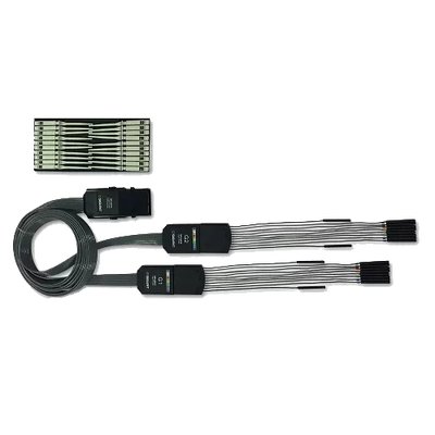
Sixteen digital channels at 500 MSa/s and 50 Mpts per channel on this series. The software is part of the current firmware.
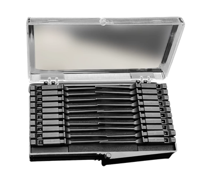
A set of 20 replacement clips in a case, for the logic probe’s flying leads.
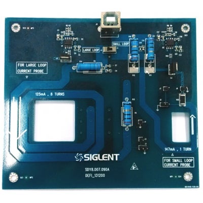
Aligns the voltage and the current probe in time before a switching-loss measurement.
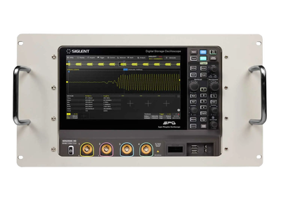
One instrument per kit; also fits the SDS1000X HD and SDS3000X HD.
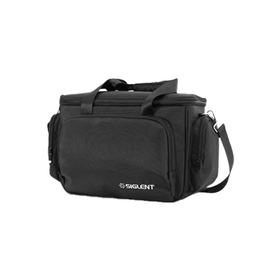
Padded bag for the oscilloscope, probes and cables.
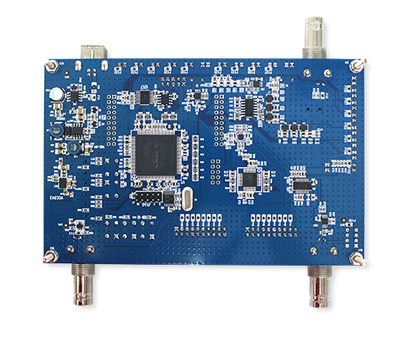
Signal source for teaching triggers and serial decode (STB3 in the data sheet).
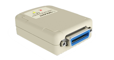
Puts the oscilloscope on an IEEE-488 bus; listed for this series in the data sheet.
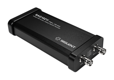
An isolated 25 MHz source for the Bode plot when the injection point must float.
Probes named in the data sheet
One high-voltage passive probe, five high-voltage differential probes and nine current probes. All connect to the BNC input and bring their own power supply.
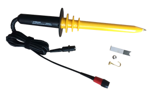
10 kV passive · 40 MHz · 1000:1
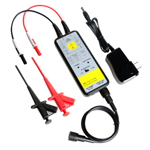
±1,300 V differential · 50 MHz
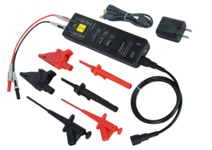
±1,500 V differential · 70 MHz
±1,500 V differential · 100 MHz
±7,000 V differential · 70 MHz
±7,000 V differential · 100 MHz
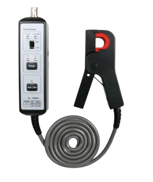
Current · 100 A peak · DC–600 kHz
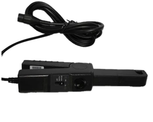
Current · 20 A rms / 60 A peak
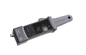
Current · 50 A rms / 140 A peak · DC–1 MHz
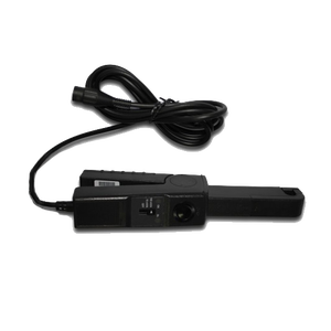
Current · 70 A rms / 200 A peak · 5 and 50 mV/A
Current · 70 A rms / 200 A peak · 10 and 100 mV/A
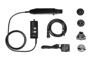
Current · 30 A rms / 50 A peak · DC–50 MHz
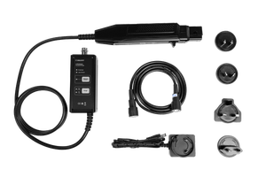
Current · 30 A rms / 50 A peak · DC–100 MHz
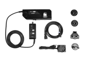
Current · 150 A rms / 300 A peak · DC–12 MHz
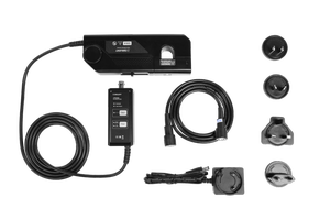
Current · 500 A rms / 750 A peak · DC–5 MHz
Specifications
From the SDS2000X HD data sheet EN02B. Typical values are not warranted.
| Models | |
| Analogue channels | 4 + external trigger |
| Bandwidth (−3 dB, 50 Ω) | SDS2204X HD 200 MHz · SDS2354X HD 350 MHz · upgradable to 500 MHz (interleaving mode) |
| Rise time (50 Ω, typ.) | 1.7 ns (200 MHz) · 1 ns (350 MHz) |
| Noise floor (rms, 50 Ω, 1 mV/div, typ.) | 55 µV (200 MHz) · 65 µV (350 MHz) |
| ENOB (typ.) | 8.6 bit (200 MHz) · 8.4 bit (350 MHz) |
| Acquisition | |
| Sample rate | 2 GSa/s interleaving (one channel of each pair C1/C2 and C3/C4) · 1 GSa/s with both channels of a pair on |
| Record length | 200 Mpts/ch interleaving · 100 Mpts/ch non-interleaving (20 / 10 Mpts in Average and ERES) |
| Resolution | 12-bit ADC · ERES adds 0.5 to 3 bits |
| Waveform capture rate | 100,000 wfm/s normal · 500,000 wfm/s Sequence |
| Sequence / History | Up to 80,000 segments or frames · 2 µs minimum between triggers |
| Peak detect / Average | 1 ns · 4 to 1,024 averages |
| Vertical | |
| Vertical scale | 0.5 mV/div to 10 V/div (1 MΩ) · 0.5 mV/div to 1 V/div (50 Ω) |
| DC gain accuracy | ±1.0 % max., ±0.5 % typ. (5 mV/div to 10 V/div) · ±1.5 % below 5 mV/div |
| Bandwidth limit | 20 MHz, 200 MHz (hardware) |
| Input | 1 MΩ ±2 % ‖ 16 pF, or 50 Ω ±1 % · max. 400 Vpk (1 MΩ), 5 Vrms (50 Ω) |
| Channel isolation | > 60 dBc below 500 MHz · > 70 dBc below 350 MHz |
| Horizontal & trigger | |
| Time base | 1 ns/div to 1,000 s/div · accuracy ±2 ppm initial, ±0.5 ppm first-year aging |
| Trigger types | Edge, Slope, Pulse, Window, Runt, Interval, Dropout, Pattern, Video (HDTV), Qualified, Nth edge, Setup/hold, Delay, Serial · Zone trigger (2 zones) |
| Trigger jitter | < 10 ps rms (typ.), C1–C4 |
| Serial trigger and decode, standard | I²C, SPI, UART, CAN, LIN |
| Serial trigger and decode, optional | CAN FD, FlexRay, I²S, MIL-STD-1553B, SENT |
| Serial decode only, optional | CAN XL, Manchester, ARINC 429, SpaceWire |
| Analysis | |
| Measurements | 60+ parameters · 12 on screen · statistics, histogram, trend, track · gating · on Math, History and Ref |
| Math | 4 traces · 2 Mpts FFT · arithmetic, integration, differentiation, filter, ERES, average · formula editor |
| Standard tools | Search, Navigate, History, Mask Test (up to 14,000 frames/s), DVM, Counter (7 digits), Waveform Histogram, Bode plot (10 Hz to 120 MHz) |
| Optional tools | Power Analysis (SDS2000HD-PA) |
| Digital channels and generator | |
| Digital channels (SPL2016) | 16 · 500 MSa/s · 50 Mpts/ch · 3.3 ns minimum pulse · thresholds −10 to +10 V in two groups (TTL, CMOS, LVCMOS 3.3/2.5, custom) |
| Waveform generator (SDS2000HD-FG) | 1 channel · 25 MHz sine, 10 MHz square/pulse, 5 MHz arbitrary · 125 MSa/s, 14-bit, 16 kpts · ±1.5 V into 50 Ω, ±3 V into high impedance |
| Display & I/O | |
| Display | 10.1-inch TFT, 1024 × 600, capacitive multi-touch · 256-level intensity grading, colour temperature mode |
| Front | 2× USB 2.0 host · logic probe port D0–D15 · calibration signal 1 kHz, 3 V |
| Rear | USB 2.0 host · USB 2.0 device (USBTMC) · LAN 10/100 (VXI-11, Telnet, Socket) · external trigger · auxiliary out (trigger out or pass/fail) |
| Remote control | Built-in web server in a browser · SCPI · external mouse and keyboard |
| General | |
| Power | 100–240 Vrms, 50/60 Hz · 120 W max., 70 W typ., 4 W standby |
| Size / weight | 317.2 × 236.0 × 149.0 mm · 4.1 kg net |
| Supplied with | One 500 MHz passive probe per channel, USB cable, power cord, quick start, calibration certificate, wireless mouse |
| Warranty | 3 years |
Where it is used
Embedded and mixed-signal
Four analogue and sixteen digital channels with I²C, SPI, UART, CAN and LIN decoded as standard — analogue cause and digital effect on one time axis.
Power supply design
Loop response with the Bode plot, switching loss and harmonics with the PA key, and Siglent’s differential and current probes for the high side.
Automotive networks
CAN and LIN standard; CAN FD, CAN XL, FlexRay and SENT as keys, decoded next to the physical layer that carries them.
Avionics and space
MIL-STD-1553B, ARINC 429 and SpaceWire decode on a bench oscilloscope of this price class.
Education and production
A 10.1-inch touchscreen that students find their way around, a web server for remote labs, and pass/fail masks with an output signal for the line.
Documentation
Firmware is in the downloads centre.
Questions we are asked
Which model do I need?
Take the bandwidth of the fastest edge you care about, not of the clock: a 200 MHz model shows 1.7 ns rise times, the 350 MHz model 1 ns. If you expect to need 350 MHz within the life of the instrument, buy the SDS2354X HD now — it costs €180 less than an SDS2204X HD plus the upgrade key.
Is the SDS2104X HD still available?
No. The 100 MHz model is no longer in Siglent’s range; the SDS2204X HD is now the entry model. Bandwidth keys and service for an SDS2104X HD you already own remain available — ask us.
What does the 500 MHz upgrade really give me?
500 MHz in interleaving mode, that is with one channel of each pair (C1 or C2, C3 or C4) switched on, at 2 GSa/s. With both channels of a pair active the oscilloscope samples at 1 GSa/s and the bandwidth is 350 MHz. For two fast signals that is exactly what you want; for four it is a 350 MHz instrument.
Do I need a licence for the digital channels?
No. Siglent includes the logic-analyser software in the current firmware of this series. You buy the SPL2016 logic probe, update the firmware if the instrument is older, and the sixteen digital channels are there.
Which serial buses are included, and which can it trigger on?
I²C, SPI, UART, CAN and LIN trigger and decode are standard. CAN FD, FlexRay, I²S, MIL-STD-1553B and SENT are keys with trigger and decode. CAN XL, Manchester, ARINC 429 and SpaceWire are keys with decode only — you trigger on the signal and read the decoded table.
Is power analysis included?
No, it is the SDS2000HD-PA key. Bode plot, Mask Test, FFT and the measurement suite are standard. For power work you also need a differential probe, a current probe and ideally the DF2001A deskew fixture.
What do I need for a Bode plot?
The function is standard; it needs a sweep source. That is the built-in generator (FG key), an SAG1021I isolated USB module, or a Siglent SDG generator over USB or LAN. The sweep runs from 10 Hz to 120 MHz depending on the source.
Tell us the signals and we will configure it
Bandwidth, the buses you decode, whether digital channels or power analysis are in the plan. We quote the oscilloscope, keys and probes as one set. Official Siglent distributor for the EU.